A2013-V-VO-C111 Gems Sensors Inc, A2013-V-VO-C111 Datasheet - Page 2
A2013-V-VO-C111
Manufacturer Part Number
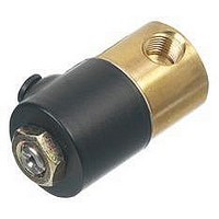
A2013-V-VO-C111
Description
Solenoid Valve
Manufacturer
Gems Sensors Inc
Datasheet
1.A2016-V-VO-C111.pdf
(2 pages)
Specifications of A2013-V-VO-C111
Orifice Size
1/16"
Operating Pressure Max
300psi
Connection Size
1/8"
Peak Reflow Compatible (260 C)
No
Port Style
NPT
Operating Power Max
6W
Leaded Process Compatible
No
Valve Type
2-Way Normally Closed
Lead Free Status / RoHS Status
Contains lead / RoHS non-compliant


Part Prefix Table
2 Coil Construction
3 Body Material
AD standard)
N.O. (option
Connection
Directional
Free Vent
Purpose
Control
2-WAY
2-WAY
3-WAY
3-WAY
3-WAY
3-WAY
3-WAY
Multi
N.C.
N.C.
N.C.
Line
N.O.
(blank) = Tape-wrapped, Class-B, with 18” lead wires*
(blank) = 303 Stainless Steel*
W___ = Tape-wrapped coil, lead-wires, non-standard length
HC2 = Encapsulated coil, Class B, EN175301-803 Form C DIN,
SB5 = 316 Stainless Steel
SBF = 430F Stainless Steel
1M = Over molded coil, Class-B, lead-wires
2M = Over molded coil, Class-F, lead-wires
3M = Over molded coil, Class-H, lead-wires
4M = Over molded coil, Class-B, 1/4” spade terminals
5M = Over molded coil, Class F, 1/4” spade terminals
6M = Over molded coil Class H, 1/4” spade terminals
HC = molded coil, Class F, EN175301-803 Form B DIN,
BB = Brass
SB = 304 Stainless Steel
10 = Externally rectified coil (lead wires only)
11 = Tape-wrapped coil, Class H, lead wires
4 = Encapsulated coil, Class-B, 3/16” spade terminals
5 = Encapsulated coil, Class-B, 0.110” spade terminals
8 = Encapsulated coil, Class F, 3/16” spade terminals
(specify length)
Industrial. 11mm, 2+1 poles
Industrial, 9.4mm, 2+1 poles
Body
1/32
3/64
1/16
5/64
3/32
5/32
1/32
3/64
1/16
1/16
3/32
1/32
3/64
1/16
1/16
3/32
1/32
3/64
1/16
1/16
3/32
1/32
3/64
1/16
1/16
3/32
1/32
3/64
1/16
1/16
3/32
1/8
—
—
—
Orifice
1
Stop
1/32
3/64
1/16
1/32
3/64
3/64
1/16
3/64
1/32
3/64
3/64
1/16
3/64
1/32
3/64
3/64
1/16
3/64
1/32
3/64
3/64
1/16
3/64
1/32
3/64
3/64
1/16
3/64
—
—
—
—
—
—
—
MOPD
(psig)
1000
500
300
200
175
100
200
150
100
200
150
100
200
150
100
150
100
125
100
225
150
100
50
75
50
75
50
90
75
50
90
75
25
75
50
0.020
0.035
0.065
0.090
0.155
0.240
0.300
0.019
0.040
0.070
0.070
0.170
0.019
0.040
0.070
0.070
0.170
0.019
0.040
0.070
0.070
0.170
0.019
0.040
0.070
0.070
0.170
0.019
0.040
0.070
0.070
0.155
Body
—
—
—
C
V
Visit www.GemsSensors.com for most current information.
0.019
0.040
0.075
0.019
0.040
0.040
0.070
0.040
0.019
0.040
0.040
0.070
0.040
0.019
0.040
0.040
0.070
0.040
0.019
0.040
0.040
0.070
0.040
0.019
0.040
0.040
0.070
0.040
Stop
—
—
—
—
—
—
—
Grommet
Housing
1 Primary Prefix
A2011
A2012
A2013
A2014
A2015
A2016
A2017
A2211
A2212
A2213
A3011
A3012
A3013
A3014
A3015
A3111
A3112
A3113
A3114
A3115
A3211
A3212
A3213
A3214
A3215
A3311
A3312
A3313
A3314
A3315
A3411
A3412
A3413
A3414
A3415
Housing
Conduit
A2021
A2022
A2023
A2024
A2025
A2026
A2027
A2221
A2222
A2223
A3021
A3022
A3023
A3024
A3025
A3121
A3122
A3123
A3124
A3125
A3221
A3222
A3223
A3224
A3225
A3321
A3322
A3323
A3324
A3325
A3421
A3422
A3423
A3424
A3425
4 Plunger Seal Material
5 O-Ring Material
6 Body Port Configuration
7 Voltage
8 Additional Options
†††
††
* Standard selection; will be used unless otherwise specified.
†
Gems specializes in the design and manufacturing of custom
solenoid valves and fluidic systems. If you don’t see what you’re
looking for, or have a question, contact us at 800-378-1600 or
info@gemssensors.com.
Plastic body available, contact Gems.
Can be AC rectified without shading ring. Use coil construction Code 10.
Teflon
Standard selections are not referenced in final part number.
___VDC = DC (specify DC voltage)
___VAC = AC (specify AC voltage; includes copper shading ring)
(blank) = Nitrile*
(blank) = Nitrile*
(blank) = 1/8-27 NPT female thread*
MM3 = Manifold mount (5/16-24 UNF-2A mounting stud)
BOM = Bottom under-seat port, 1/8-27 NPT male thread
®
NSO = Nitrile (NSF/FDA, 2-way valves only)
PFO = Perfluoroelastomer
BIM = Bottom over-seat port, 1/8-27 NPT male thread
WM = Mounting bracket
VAC = Vacuum application (0 to 29.5˝ Hg)
MM = Manifold mount (1/4-28 UNF-2A mounting stud)
o-ring not suitable for manifold mount.
MB = Bottom metering (max. orifice = 3/32˝)
NO = Neoprene
RR = 90° porting - right hand
QO = Quiet operation (2-way valves only)
GV = Gasoline Viton
NS = Nitrile (NSF/FDA, 2-way valves only)
EO = EPR
TO = PTFE
VO = Viton
BD = #10-32 female straight thread (max. orifice = 1/8˝)
LU = 1/4-19 BSPT female thread (2-way valves only)
OB = Omit body (operator style)
BO = Bottom under-seat port, female thread
RL = 90° porting - left hand
BS = Stop port, #10-32 female straight thread
AD = 1/8 - 27 NPT stop port adapter (3-way valves only)
OC = Cleaned for oxygen use
G1 = One-piece 303 Stainless Steel guide assembly
G5 = One piece 316 Stainless Steel guide assembly
PF = Perfluoroelastomer
LB = 1/4-18 NPT female thread
TP = PTFE coated plunger
LT = 1/8-28 BSPT female thread (2-way valves only)
BI = Bottom over-seat port, female thread
††
N = Neoprene
R = Rulon
V = Viton
Y = Yoke
S = Silver shading ring
E = EPR
T = PTFE
(see note below)
(max. orifice = 1/8˝)
(max orifice = 5/64˝) brass body only
(max orifice = 1/8˝) brass body only
®
®
®
(2-way valves only)
®
(2-way valves only)
GENERAL PURPOSE
†
†††
†††
J-12
Related parts for A2013-V-VO-C111
Image
Part Number
Description
Manufacturer
Datasheet
Request
R

Part Number:
Description:
Solenoid Valve
Manufacturer:
Gems Sensors Inc
Datasheet:

Part Number:
Description:
CONN BACKSHELL DB15 DIE CAST
Manufacturer:
Tyco Electronics
Datasheet:

Part Number:
Description:
FLOAT LEVEL MULTI STAINLESS SENSORS
Manufacturer:
Gems Sensors Inc
Part Number:
Description:
LS-77700 316 Stainless Steel ,Buna-N, 20 VA, .84 Sp.Gr.
Manufacturer:
Gems Sensors Inc

Part Number:
Description:
LIQUID LEVEL SENSOR
Manufacturer:
Gems Sensors Inc
Datasheet:
Part Number:
Description:
SAF PAK 95-135 VAC
Manufacturer:
Gems Sensors Inc
Datasheet:
Part Number:
Description:
LS-77700 316 Stainless Steel ,Buna-N, 20 VA, .84 Sp.Gr.
Manufacturer:
Gems Sensors Inc