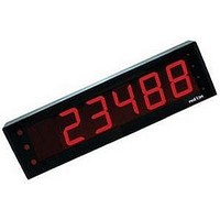
MPAXP000 Red Lion Controls, MPAXP000 Datasheet - Page 12

MPAXP000
Manufacturer Part Number
MPAXP000
Description
Process Input Module
Manufacturer
Red Lion Controls
Specifications of MPAXP000
Accessory Type
Analog Input Module
Signal Input Type
Process/Control
No. Of Analog Outputs
5
No. Of Analog Inputs
5
Accuracy
0.03% of reading +2 μA, 0.03% of reading +2 mV
Brand/series
MPAX Series
Display Type
LED
Impedance, Input
20 Ohms to 500 Kiloohms
Measuring Range
-2 to 26 mA, -1 to 13 VDC
Resolution
16 Bit
Standards
cULus Listed, CE Certified
Voltage, Working
85 to 250 VAC
Sealing
NEMA 4/IP65
For Use With
EPAX 5 Digit Displays
Lead Free Status / RoHS Status
Lead free / RoHS Compliant
3.2 INPUT SIGNAL WIRING
Resistance Signal
(3 wire requiring
excitation)
Terminal 3: Resistance
Terminal 5: Resistance
Terminal 6: Jumper to
Excitation Jumper:
PAXD INPUT SIGNAL WIRING
PAXP INPUT SIGNAL WIRING
Voltage Signal
Terminal 3: +VDC
Terminal 5: -VDC
Voltage Signal
Terminal 3: +VDC
Terminal 5: -VDC
Before connecting signal wires, the Input Range Jumper and Excitation Jumper should be verified for proper position.
(self powered)
1.75 mA REF.
(self powered)
terminal 3
CAUTION: Sensor input common is NOT isolated from user input common. In order to preserve the safety of the meter application, the sensor input
common must be suitably isolated from hazardous live earth referenced voltages; or input common must be at protective earth ground potential. If not,
hazardous live voltage may be present at the User Inputs and User Input Common terminals. Appropriate considerations must then be given to the
potential of the user input common with respect to earth common; and the common of the isolated plug-in cards with respect to input common.
Current Signal
(self powered)
Terminal 4: +ADC
Terminal 5: -ADC
Current Signal
(self powered)
Terminal 4: +ADC
Terminal 5: -ADC
Current Signal (2 wire
requiring excitation)
Terminal 4: -ADC
Terminal 6: +ADC
Excitation Jumper: 24 V
Current Signal (2 wire
requiring excitation)
Terminal 4: -ADC
Terminal 6: +ADC
11
Potentiometer Signal
(3 wire requiring excitation)
Terminal 3: Wiper
Terminal 5: Low end of pot.
Terminal 6: High end of pot.
Excitation Jumper: 2 V REF.
Input Range Jumper: 2 Volt
Module 1 Input Range: 2 Volt
Note: The Apply signal scaling style
should be used because the signal will
be in volts.
Current Signal (3 wire
requiring excitation)
Terminal 4: +ADC (signal)
Terminal 5: -ADC (common)
Terminal 6: +Volt supply
Excitation Jumper: 24 V
Voltage Signal (3 wire
requiring excitation)
Terminal 3: +VDC (signal)
Terminal 5: -VDC (common)
Terminal 6: +Volt supply
Excitation Jumper: 24 V
Current Signal (3 wire
requiring excitation)
Terminal 4: +ADC (signal)
Terminal 5: -ADC (common)
Terminal 6: +Volt supply
Voltage Signal (3 wire
requiring excitation)
Terminal 3: +VDC (signal)
Terminal 5: -VDC (common)
Terminal 6: +Volt supply


