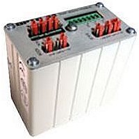
SNAP-B3000-MODBUS OPTO 22, SNAP-B3000-MODBUS Datasheet - Page 11

SNAP-B3000-MODBUS
Manufacturer Part Number
SNAP-B3000-MODBUS
Description
G4 DIGITAL I/O MODULE
Manufacturer
OPTO 22
Type
PC Basedr
Specifications of SNAP-B3000-MODBUS
Leaded Process Compatible
No
Peak Reflow Compatible (260 C)
No
Brand/series
SNAP Series
Communication
RS-422/485
Current, Input
1 A
Dimensions
3.3"L×1.82"W×3.62"H
Input Type
Analog/Digital
Mounting Type
Rack
Number Of Expansion Modules
8, 12/16
Number Of Inputs
32
Number Of Outputs
32
Output Type
Analog/Digital
Primary Type
Controller
Terminal Type
2/4 Wire
Termination
2/4 Wire
Voltage, Supply
5-5.2 VDC
Lead Free Status / RoHS Status
Contains lead / RoHS non-compliant
For Use With
I/O Rack
Modbus Analog and Digital SNAP Brain
SNAP-B3000-Modbus I/O Configuration (Continued)
Tables of Configuration Types, Values, and Scaling
(Continued)
Steps for Using SNAP-B3000-MODBUS
1. Configure the modules by writing the appropriate module con-
2. Store the module configuration to flash by writing the value 1
3. Cycle power to the brain so that it will boot up with the values
SNAP-AIMA2-i
SNAP-AIRATE
Raw counts
–1 to +1 mA
Raw counts
0 to 25,000 kHz
© 2007 Opto 22. All rights reserved. Dimensions and specifications are subject to change. Brand or product names used herein are trademarks or registered trademarks of their respective companies or organizations.
figuration codes to Holding Registers 33 through 48 (decimal).
to Holding Register 65 (decimal).
stored to flash.
SALES 800-321-6786 • 951-695-3000 • FAX 951-695-3095 • sales@opto22.com • SUPPORT 800-835-6786 • 951-695-3080 • FAX 951-695-3017 • support@opto22.com
Position
Analog Points - Two-channel Input Points
page
Module
(See
10
12
13
14
15
Module
11
0
1
2
3
4
5
6
7
8
9
8)
(See
SNAP-AOA-23
SNAP-AOA-23
SNAP-AOV-27
SNAP-AOV-27
Digital Output
SNAP-AICTD
Digital Output
Digital Output
Module Part
SNAP-AITM
SNAP-AITM
SNAP-AITM
SNAP-AITM
SNAP-AITM
Digital Input
Digital Input
SNAP-AIV
Numbers
page
10)
85
69
0
0
Registers
55
45
Holding
0
0
page
(See
33
34
35
36
37
38
39
40
41
42
43
44
45
46
47
48
1000
9)
1
1
1
(See
Register Data
x
x
Holding
page
256
384
128
131
384
384
256
128
167
19
68
66
11
4
5
8
Opto 22 • 43044 Business Park Drive • Temecula, CA 92590-3614 • www.opto22.com
4. Read the module configuration values from Holding Registers
10)
SNAP-AIVRMS
SNAP-AIARMS
Raw counts
0 to 250 V RMS
Raw counts
0 to 10 A RMS
Both points on a module must be configured the same. The fol-
lowing table shows a sample system:
33 through 48 (decimal) to confirm that the values were stored
to flash.
(1000) x (voltage signal)
(1000) x (mA signal)
(1000) x (mV signal)
(1000) x (mV signal)
(100) x (Degrees C)
(10) x (Degrees C)
(10) x (Degrees C)
(10) x (Degrees C)
(1000) x (V signal)
Analog Points - Two-channel Input Points
Module Data
Raw Counts
Raw counts
Module
Type K Thermocouple
Type E Thermocouple
Type J Thermocouple
-150 to +150 mV
70
71
-10 to +10 VDC
-10 to +10 VDC
0
0
-75 to +75 mV
-5 TO +5 VDC
ICTD Sensor
Signal Type
4 to 20 mA
4 to 20 mA
46
47
0
0
1000
100
1
1
x
x
PAGE
11


