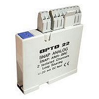
SNAP-AIPM-3 OPTO 22, SNAP-AIPM-3 Datasheet - Page 5

SNAP-AIPM-3
Manufacturer Part Number
SNAP-AIPM-3
Description
Power Monitoring Module
Manufacturer
OPTO 22
Datasheet
1.SNAP-AIPM.pdf
(21 pages)
Specifications of SNAP-AIPM-3
Accessory Type
Three-phase Power Monitoring Module
Signal Input Type
85 To 250V And 0 To 10A RMS
No. Of Analog Inputs
4
Rohs Compliant
Yes
For Use With
Snap I/O Modules
Lead Free Status / RoHS Status
Lead free / RoHS Compliant
SNAP Power Monitoring Modules
© 2006–2011 Opto 22. All rights reserved. Dimensions and specifications are subject to change. Brand or product names used herein are trademarks or registered trademarks of their respective companies or organizations.
Important Notes on Wiring
Wiring should be done by a licensed electrician. Be sure to use
appropriate CTs, and never mix CT types on the same device.
The wrong CT can cause severe damage to equipment.
For the SNAP-AIPM-3V module, suitable CTs with a 0.333 VAC
secondary are available from Opto 22. See form #1938, the
Split-Core Current Transformers Data
information.
Input Resistance – Single
Ended
Maximum Input
Calculated Channels
True Power and Volt-Amps
Range
Over Range
Accuracy:
Resolution
AC Common Mode Rejec-
tion
Maximum Operating Com-
mon Mode Voltage
Power Requirements
Ambient Temperature:
Agency Approvals
Warranty
Calculated Outputs
True Power
Volt Amps
1-second Energy Sum
1-second abs Energy Sum
*Inputs on older modules were 0–250 V and for SNAP-AIPM-3, 0–10 A. Before wiring or scaling, check printed information on the
module to make sure you are using the correct voltage and current. Contact Opto 22 Product Support with any questions.
**Values depend on CT selection.
True Power
Volt-Amps
Operating
Storage
SALES 800-321-6786 • 951-695-3000 • FAX 951-695-3095 • sales@opto22.com • SUPPORT 800-835-6786 • 951-695-3080 • FAX 951-695-3017 • support@opto22.com
0.005 Ohm
NOTE: Because both channels share the same
reference terminal, polarity must be observed
when connecting the voltage channel.
15 A continuous, non-operating
True power: 1500.0 Watts. Volt-amps: 1500.0
volt-amps
(inputs = 300 volts and 5 amps)
1650 Watts true power or 16,500 counts volt-
amps
± 0.6% reading (at full scale = ± 15 Watts)
± 0.6% reading (at full scale = ± 15 VA)
100 mW with default scaling
> –120 dB at 60 Hz
300 VAC
5.0 VDC ± 0.15 VDC at 100 mA
0 to 70 °C
-25 to 85 °C
CE, RoHS, DFARS
Lifetime
0–1500 W (from synchronous measurement of
volts and amps)
0–1500 VA (VRMS x ARMS)
0–4500 joules (true power sum ABC, signed)
0–4500 joules (true power sum of absolute
value of each A, B, and C, always positive)
Sheet, for more
SNAP-AIPM-3
IMPORTANT—Voltage change: Older SNAP-AIPM-3 and
SNAP-AIPM-3V modules (manufactured before April 2011)
were designed with an input range of 0–250 volts (not 0–300
V) for points 0, 4, and 8. Older SNAP-AIPM-3 modules used 0–
10 A (not 0–5). Before wiring or scaling, check the printed
information on the module to make sure you are using the
correct voltage and current. Older modules can be exchanged
for newer ones; contact Product Support for information.
Wiring diagrams begin on
Opto 22 • 43044 Business Park Drive • Temecula, CA 92590-3614 • www.opto22.com
500 K Ohms
NOTE: Because both channels share the same
reference terminal, polarity must be observed
when connecting the voltage channel.
5 VAC continuous, non-operating
True power and volt-amps are calculated from
300 volts and the full-scale current input of your
0.333 VAC output CT.
Depends on CT selection
± 0.6% reading
± 0.6% reading
Depends on CT selection
> –120 dB at 60 Hz
300 VAC
5.0 VDC ± 0.15 VDC at 100 mA
0 to 70 °C
-25 to 85 °C
CE, RoHS, DFARS
Lifetime
W (from synchronous measurement of volts
and amps)**
VA (VRMS x ARMS)**
Joules (true power sum ABC, signed)**
Joules (true power sum of absolute value of
each A, B, and C, always positive)**
page
SNAP-AIPM-3V
10.
PAGE
5


