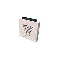
SNAP Analog Input Modules
Description
SNAP I/O analog input modules are part of
Opto 22’s SNAP PAC System. All of these
modules mount on a SNAP PAC rack with a
SNAP PAC brain or R-series controller.
A minimum number of SNAP module types
support a full range of analog input
requirements. These software-configurable
modules handle a wide variety of signal levels.
They provide high resolution (0.004% of
nominal range) for precise signal levels, as well
as multiple-channel packaging. All SNAP analog
modules are factory calibrated and individually
tested. Part numbers ending in -FM are Factory
Mutual approved.
SNAP analog input modules have an on-board
microprocessor to provide module-level
intelligence, which makes them an ideal choice
for Original Equipment Manufacturers (OEMs).
For additional information about the standalone
operation of SNAP analog modules, see Opto 22
form #0876, SNAP I/O Module Integration Guide.
Notes for legacy hardware: Some of these
modules also work with older Opto 22 I/O
processors (brains or on-the-rack controllers)
and M-series or B-series racks. To check
processor compatibility, see the table on
Specifications begin on
drawings, see pages 28–36.
IMPORTANT: Any system using analog sensors
and input modules should be calibrated
annually for analog signals. For I/O units on a
SNAP PAC System, use the PAC Control
commands “Calculate and Set Offset” and
“Calculate and Set Gain.” For other Ethernet-
based I/O units, you can also use PAC Manager
software to calculate and set offset and gain.
Features
Resolution = 0.004% of nominal range
Two, 4, 8, or 32 single-ended inputs per module
Out-of-range indication
Operating temperature 0 °C to 70 °C
Factory calibrated; no user adjustment necessary
page
3. For dimensional
™
page
2.
™
Part Number
SNAP-AIARMS
SNAP-AIVRMS
SNAP-AIMA
SNAP-AIMA-4
SNAP-AIMA-8
SNAP-AIMA-32
SNAP-AIMA-32-FM*
SNAP-AIRATE
SNAP-AIRTD
SNAP-AICTD
SNAP-AICTD-4
SNAP-AICTD-8
SNAP-AITM
SNAP-AITM-2
SNAP-AITM-8
SNAP-AITM-8-FM*
SNAP-AIV
SNAP-AIV-4
SNAP-AIV-8
SNAP-AIV-32
SNAP-AIV-32-FM*
SNAP-AIMV-4
SNAP-AIMV2-4
SNAP-AIR40K-4
* Factory Mutual approved
Part
SNAP Analog Input Modules
2-channel 0 to 10 amp RMS AC/DC input
2-channel 0 to 250 V RMS AC/DC input
2-channel analog current input, -20 to +20 mA
4-channel analog current input -20 to +20 mA
8-channel analog current input -20 to +20 mA
32-channel analog current input -20 to +20 mA
2-channel 0–25,000 Hz analog rate input
2-channel 100-ohm platinum RTD input
2-channel analog temperature input, ICTD
4-channel analog temperature input, ICTD
8-channel analog temperature input, ICTD
2-channel analog type E, J, or K thermocouple or -150
to +150 mV input or -75 to +75 mV input
2-channel analog type B, C, D, G, N, T, R, or S thermo-
couple or -50 to +50 mV DC or -25 to +25 mV DC input
8-channel B, C, D, E, G, J, K, N, R, S, or T thermocou-
ple or -75 to +75 mV, -50 to +50 mV, or -25 to +25 mV
input
2-channel analog voltage input -10 to +10 VDC or -5 to
+5 VDC
4-channel analog voltage input -10 to +10 VDC or -5 to
+5 VDC
8-channel analog voltage input -10 to +10 VDC or -5 to
+5 VDC
32-channel analog voltage input -10 to +10 VDC or -5
to +5 VDC
4-channel -150 to +150 mV input or -75 to +75 mV
input
4-channel -50 to +50 mV input or -25 to +25 mV input
4-channel analog resistor/thermistor input, 40 K ohms,
20 K ohms, 10 K ohms, or 5 K ohms
Description
page
See
10
11
14
21
18
19
20
23
23
25
26
16
17
13
3
4
8
8
5
5
7
PAGE
1


