IFMR0036 Red Lion Controls, IFMR0036 Datasheet - Page 7
IFMR0036
Manufacturer Part Number
IFMR0036
Description
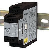
Isolation Amplifier
Manufacturer
Red Lion Controls
Type
Speedr
Specifications of IFMR0036
Width
3.12"
Signal Input Type
Selectable Current Or Voltage
Configuration Setup
DIP Switch
Supply Voltage Max
32VDC
Iso-amp Mounting Type
DIN Rail
Display Alarm Type
Relay
Input Accuracy
± 0.1% Of FS
Application
The IFMR utilizes a seven position DIP switch, a rotary switch, a pushbutton and two indication LEDs to accomplish input circuit configuration, operational parameter set-up, input signal, and relay status indication
Brand/series
IFMR Series
Contact Form
SPDT
Current Rating
5 A
Dimensions
27.5mmW×4.2mmH×79.2mmD
Display Type
LED
Input Type
Analog
Mounting Type
DIN Rail
Output Type
Relay
Power, Rating
2 W
Primary Type
Controller
Sensor, Input
12 VDC
Standards
cURus, CE
Temperature, Operating
0 to +50 °C
Termination
Screw
Voltage, Rating
9 to 32 VDC
Voltage, Supply
9-32 VDC
Signal Output Type
Current
Rohs Compliant
Yes
Lead Free Status / RoHS Status
Lead free / RoHS Compliant
For Use With
Sensors/Switches/TTL


5.0 Set Relay Trip Point (Offset)
6.0 Set Relay Release Point (Hysteresis)
BLINKS
OUTPUT
BLINKS
OUTPUT
GREEN
INPUT
GREEN
INPUT
LED
LED
RED
LED
OFF
RED
LED
OFF
O U
O U
IN
IN
T
T
Step 6.2
Step 5.2
Step 6.3
Step 5.3
Step 5.4
Step 6.4
PUSH-BUTTON
PUSH-BUTTON
ROTARY
SWITCH
ROTARY
SWITCH
Setting ‘9’
Setting ‘9’
4
4
Selected
Selected
Step 5.1
Step 6.1
5
0
5
5
0
5
6
6
7
7
Hysteresis value. For Underspeed operation, the Relay Release point is set to the Relay Trip point
plus the Hysteresis value. The hysteresis value is calculated by multiplying the hysteresis
percentage by the current trip frequency. If No Hysteresis (setting = 0) is selected, the Relay Trip
and Release points are identical, which can lead to chattering or cycling of the relay at input
frequencies hovering around the Relay Trip point.
Example: Using the Trip Frequency and Offset value as shown in the example above, the
6.1 Place DIP switch 4 to the ON position and DIP switches 5, 6, and 7 as shown.
6.2 The Green input LED blinks the existing setting (see following list), pauses, and repeats.
6.3 Press the push-button. The Green input LED blinks rapidly. Trip Point Hysteresis setting is
6.4 Turn the rotary switch to the selected numerical value for Hysteresis desired (see list in Step 6.2).
6.5 Press the push-button. The Green input LED blinks the value entered, pauses and repeats the
*
Offset value. For Underspeed operation, the Relay Trip point is internally set to the Trip Frequency
minus the Offset value. The Offset value is equal to the Trip Frequency multiplied by the selected
Offset percentage.
Example: The Offset value is calculated as shown below.
5.1 Place DIP switch 4 to the ON position and DIP switches 5, 6, and 7 as shown.
5.2 The Green input LED blinks the existing setting (see following list), pauses and repeats.
5.3 Press the push-button. The Green input LED blinks rapidly. Trip Point Offset setting is now
5.4 Turn the rotary switch to the selected numerical value for Trip Point Offset desired (see list in
5.5 Press the push-button. The Green input LED blinks the value entered, pauses, and repeats the
*
Section complete; place DIP switch 4 to the down position for normal operation, or change DIP
hysteresis value is calculated as shown below.
Rotary Switch Setting =
Hysteresis Value
Release Point:
If the new Trip Point Hysteresis setting is acceptable, this section is complete
If the new Trip Point Hysteresis setting is not the desired setting, repeat Steps 6.3, 6.4, and 6.5.
and 6.5.
switches 5, 6, and 7 for the next Configuration Section.
Section complete; place DIP switch 4 to the down position for normal operation, or change DIP
If the Red relay LED blinks, the rotary switch numerical value is invalid. Repeat Steps 6.4
Trip Frequency
Rotary Switch Setting =
Offset Value
Trip Point:
If the new Trip Point Offset setting is acceptable, this section is complete
and 5.5.
switches 5, 6, and 7 for the next Configuration Section.
For Overspeed operation, the Relay Release point is set to the Relay Trip point minus the
For Overspeed operation, the Relay Trip point is internally set to the Trip Frequency plus the
If the new Trip Point Offset setting is not the desired setting, repeat Steps 5.3, 5.4, and 5.5.
If the Red relay LED blinks, the rotary switch numerical value is invalid. Repeat Steps 5.4
now accessed.
new setting.
accessed.
Step 5.2).
new setting.
Setting
OVERSPEED
UNDERSPEED
OVERSPEED
UNDERSPEED
Setting
0
1
2
3
4
5
6
7
8
9
0
1
2
3
4
5
6
7
8
9
7
Percentage
0.00% (NO Offset)
0.25% (0.0025)
0.50% (0.0050)
1.00% (0.0100)
2.00% (0.0200)
5.00% (0.0500)
10.00% (0.1000)
20.00% (0.2000)
25.00% (0.2500)
33.33% (0.3333)
Percentage
0.00% (NO Hysteresis)
0.25% (0.0025)
0.50% (0.0050)
1.00% (0.0100)
2.00% (0.0200)
5.00% (0.0500)
10.00% (0.1000)
20.00% (0.2000)
25.00% (0.2500)
33.33% (0.3333)
=
=
=
=
=
=
=
3 (1.00%)
250 Hz x 1.00% (0.01) = 2.5 Hz
250 + 5 - 2.5 = 252.5 Hz
250 - 5 + 2.5 = 247.5 Hz
250 Hz
4 (2.00%)
250 Hz x 2.00% (0.02) = 5 Hz
250 + 5 = 255 Hz
250 - 5 = 245 Hz
*
.
*
.
Related parts for IFMR0036
Image
Part Number
Description
Manufacturer
Datasheet
Request
R

Part Number:
Description:
Counter
Manufacturer:
Red Lion Controls
Datasheet:
Part Number:
Description:
Miniature Length Sensor
Manufacturer:
Red Lion Controls
Datasheet:
Part Number:
Description:
Model Lsc - Single Channel Output Length Sensor
Manufacturer:
Red Lion Controls
Datasheet: