KFA5-SR2-EX1.W PEPPERL & FUCHS, KFA5-SR2-EX1.W Datasheet
KFA5-SR2-EX1.W
Manufacturer Part Number
KFA5-SR2-EX1.W
Description
Isolator Relay
Manufacturer
PEPPERL & FUCHS
Datasheet
1.KFA5-SR2-EX1.W.pdf
(1 pages)
Specifications of KFA5-SR2-EX1.W
Isolation Input
Isolated
Mounting
DIN Rail
No. Of Channels
1
Supply Voltage
115VAC
Dc / Dc Converter O/p Type
Relay
Signal Conditioner Mounting
DIN Rail
Rohs Compliant
Yes
Lead Free Status / RoHS Status
Lead free / RoHS Compliant
USA Headquarters
phone: 330 486-0002 • email: sales@us.pepperl-fuchs.com
Connection Diagram
Technical Data
POWER SUPPLY
INPUT (intrinsically safe)
OUTPUT (not intrinsically safe)
TRANSFER CHARACTERISTICS
CERTIFICATES
MECHANICAL
AMBIENT TEMPERATURE
Class I; Div 1, 2
Zone 0, 1, 2
Nominal voltage
Power Consumption
Nominal Data
Input pulse length/interval
Lead Breakage (LB) Monitoring
Output 1 (SPDT contacts)
Contact load
Mechanical life
Energizing/de-energizing delay
Switching Frequency
Housing
Dimensions
Weight
LB/SC
Input 1
Hazardous Area
web: www.am.pepperl-fuchs.com
Latest Info. Avail. Online
LB/SC
Engineer's Guide (page 7)
Surge Suppression (page 413)
Accessories (page 443)
R
2
R
1
LB
R
1
Zone 0, 1, 2
Exida
1
2
3
PTB 00 ATEX 2081,
Breakage I ≤ 0.1 mA, short-circuit I > 6 mA
4.65" x 0.79" x 4.53" (118 x 20 x 115 mm)
Worldwide Headquarters
phone: +49 621 776-0 • email: pa-info@de.pepperl-fuchs.com
Safe Area or Div 2
See page 127 for entity parameters
-4°F to +140°F (-20°C to +60°C)
KFA5-SR2-Ex1.W
126.5 VAC/4 A/cos ø > 0.7;
40 VDC/2 A resistive load
253 VAC/2 A/cos ø > 0.7;
Type C see page 454
10
Terminals 1+, 2+, 3-
P+F 02/4-12 R007
≥ 20 ms/≥ 20 ms
≈ 20 ms/≈ 20 ms
Terminals 14, 15
Terminals 7, 8, 9
115 VAC ± 10%
≈ 8 VDC/≈ 8 mA
5.3 oz. (≈ 150 g)
7
No. 116-0145
No. 116-0035
No. 116-0047
switching cycles
< 10 Hz
1 W
web: www.pepperl-fuchs.com
II (1) G D [EEx ia] IIC
14
15
8
7
9
}
}
Supply
120 VAC
Relay
Output
Model Number
KFA5-SR2-Ex1.W
• 1-channel
• 120 VAC supply
• Suitable for Division 2 mounting
• 1 signal output with 1 form C relay
• Optional lead breakage (LB) and short
• SIL 2 according to IEC 61508; SIL 3 in a
This device is a single-channel, galvanically isolated
intrinsic safety barrier that transfers discrete signals
(NAMUR sensors/mechanical contacts) from a hazardous
area to a safe area. The proximity sensor or switch controls
a form C relay contact for the safe area load. The barrier
output changes state when the input signal changes state.
This output state can be reversed through the mode of
operation switch S1.
For a mechanical contact, LB monitoring can be selected
by placing a 10 kΩ resistor across the mechanical contact
in the field and moving switch S3 to position I on the
barrier. SC monitoring is added by placing a 400Ω-2 kΩ
resistor in series with the mechanical contact. NAMUR
proximity sensors, however, are designed with the LB and
SC functions, making external resistors unnecessary. In
case of a LB/SC fault, the signal output relay reverts to the
deenergized state. LB/SC monitoring can be disabled with
S3 in position II.
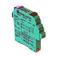
Front View
Housing type C
(see system description)
LED yellow:
Relay output
LED red:
LB/SC
Switch S2
(no functions)
1-Channel with
Relay Output
circuit (SC) monitoring
redundant structure
Asia Pacific Headquarters
phone: +65 67799091 • email: sales@sg.pepperl-fuchs.com
KFA5-SR2-Ex1.W
web: www.pepperl-fuchs.com
Removable terminal
blue
Switch S3
(LB/SC-monitoring)
Removable terminals
green
LED green:
Power supply
Switch S1
(Mode of operation)
111
Related parts for KFA5-SR2-EX1.W
Image
Part Number
Description
Manufacturer
Datasheet
Request
R


Part Number:
Description:
SINGLE CHANNEL, 2 FORM C RELAY OUTPUTS, SELECTABLE LINE MONITORING W/COMMON FAU
Manufacturer:
PEPPERL & FUCHS
Part Number:
Description:
WE77/EX-1 230V, PEPPERL + FUCHS, SWITCH ISOLATOR 230V
Manufacturer:
PEPPERL & FUCHS
Datasheet:
Part Number:
Description:
Rotary Encoders - Absolute
Manufacturer:
PEPPERL & FUCHS


Part Number:
Description:
LED Pilot Light
Manufacturer:
PEPPERL & FUCHS
Datasheet:

Part Number:
Description:
LED Pilot Light
Manufacturer:
PEPPERL & FUCHS
Datasheet:
Part Number:
Description:
LED Pilot Light
Manufacturer:
PEPPERL & FUCHS
Datasheet:
Part Number:
Description:
LED Pilot Light
Manufacturer:
PEPPERL & FUCHS
Datasheet: