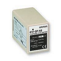
61FGPN8H240AC Omron, 61FGPN8H240AC Datasheet - Page 5

61FGPN8H240AC
Manufacturer Part Number
61FGPN8H240AC
Description
LEVEL CONTROLLER
Manufacturer
Omron
Datasheet
1.61FGPN8110AC.pdf
(18 pages)
Specifications of 61FGPN8H240AC
Supply Voltage
240VAC
Response Time
80ms
Power Consumption
3.5VA
Svhc
No SVHC (15-Dec-2010)
Approval Bodies
CE, CSA, UL Recognised
Dielectric Strength Vac
2000VAC
External Depth
70mm
External Length /
RoHS Compliant
Liquid Level Indication
(Connection Example)
• Terminals 6 and 7, and terminals 10 and 11 on the lower -limit 61F-GP-N are shorted when the water level reaches E
• Terminals 6 and 7, and terminals 10 and 11 on the intermediate 61F-GP-N are shorted when the water level reaches E
• Terminals 6 and 7, and terminals 10 and 11 on the upper-limit 61F-GP-N are shorted when the water level reaches E
Connections
Principles of Operation
Commercial Voltage
Note: The power supply phases (terminals 3 to 9) can be matched to use the same ground for the
R S
common Electrode (the longest Electrode, terminal 4).
T
M
MCCB
http://www.ia.omron.com/
61F-GP-N
10
8
3
Power
supply
0 V
Lower limit
11
7
24 V
8 V
U
P
U
6
1
Control
circuit
(See note.)
2
Water supply
5
4
9
source
U
Liquid Level Indication
61F-GP-N
10
8
3
Power
supply
0 V
Intermediate
11
7
24 V
8 V
U
U
1
6
Control
circuit
(c)Copyright OMRON Corporation 2007 All Rights Reserved.
4
5
9
2
U
61F-GP-N
Water
tank
10
8
3
Compact, Plug-in Type
61F-GP-N
Power
supply
0 V
Dimensions:
page 14
Upper limit
11
7
E
4
24 V
8 V
E
U
3
U
1
6
E
2
Control
E
circuit
1
61F-GP-N@
1
3
4
5
9
2
(indicator ON).
(indicator ON).
2
PS-4S
(indicator ON).
U
Upper limit
Intermediate
Lower limit
5


