SS-39100-002 Stewart Connector, SS-39100-002 Datasheet
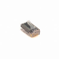
CONN 8-8 MOD PLUG CAT6

SS-39100-002

Manufacturer Part Number
SS-39100-002
Description
CONN 8-8 MOD PLUG CAT6
Manufacturer
Stewart Connector
Series
39r
Datasheets

Specifications of SS-39100-002

Connector Type
Plug
Number Of Positions/contacts
8p8c (RJ45, Ethernet)
Cable Type
Round Cable, Solid or Stranded Wires
Ratings
Cat6
Shielding
Unshielded
Termination
IDC
Length
0.845"(21.46mm)
Color
Translucent - Clear
Lead Free Status / RoHS Status
Lead free / RoHS Compliant
Other names
380-1014
Bel Stewart Connector
4.
Insert outer pairs of conductors into
loadbar as shown.
1.
Remove 1.25” (31.8 mm) of cable
jacket. Slit both sides of jacket back
.375” (9.5 mm). The slits should be
located where the two outer pairs
exit jacket. Separate the pairs.
7.
Push loadbar back onto cable until
the edge of jacket is even with the
notch in the loadbar. Pull any slack
out of the conductors. Twist should
be as close to loadbar as possible
for best performance
MN390008 A1
39 Series Plug Termination Instructions
5.
Turn assembly over and insert
center pair into loadbar.
2.
Arrange pairs according to appropriate
wiring diagram (see back of sheet). If
pairs need to be crossed, keep twisted
and cross inside jacket.
8.
Ensure that all conductors are flat
and straight in loadbar area. Trim
all conductors flush with edge of
loadbar.
ORANGE PAIR
BROWN PAIR
11118 Susquehanna Trail South
Glen Rock, PA 17327-9199
Tel: 717-25-7512 • Fax: 717-235-7954
www.stewartconnector.com
6.
Turn assembly back. Trim the last
pair slightly to make loading easier
and insert into loadbar.
3.
Straighten conductors and align per
diagram Only untwist enough
conductors to allow insertion into
loadbar.
9.
Insert loadbar into the housing and
terminate.

Related parts for SS-39100-002

SS-39100-002 Summary of contents

Page 1

... Push loadbar back onto cable until the edge of jacket is even with the notch in the loadbar. Pull any slack out of the conductors. Twist should be as close to loadbar as possible for best performance MN390008 A1 2. BROWN PAIR ORANGE PAIR Arrange pairs according to appropriate wiring diagram (see back of sheet) ...

Page 2

... As with all wiring installation and modification, the following statements apply: Use caution and common sense when installing, modifying, or removing any communication wiring and systems. Never install communications wiring in wet locations unless electronic components and jacks are specifically designed for wet environments. Always disconnect communication lines from the network interface before touching uninsulated communications wiring or terminals ...

Related keywords