45593-1600 Molex Inc, 45593-1600 Datasheet - Page 11
45593-1600
Manufacturer Part Number
45593-1600
Description
CONN PLUG 16POS .8MM VERT PCB
Manufacturer
Molex Inc
Series
HandyLink™ 45593r
Specifications of 45593-1600
Connector Style
Plug
Connector Type
Handylink
Number Of Positions
16
Mounting Type
Through Hole
Termination
Solder
Contact Finish
Gold
Color
Black
Housing Material
Thermoplastic, High Temperature
Insulation Resistance
1000 M Ohms
Mounting Angle
Vertical
Operating Temperature Range
- 40 C to + 85 C
Number Of Positions / Contacts
16
Pitch
0.8 mm
Contact Plating
Gold, Tin
Contact Material
High Performance Alloy (HPA)
Gender
Male
Current Rating
1.5 A
Mounting Style
Through Hole
Termination Style
Solder
Lead Free Status / RoHS Status
Lead free / RoHS Compliant
Features
-
Contact Finish Thickness
-
Lead Free Status / Rohs Status
Lead free / RoHS Compliant
Other names
045593-1600
045593-1600-E
0455931600
0455931600-E
45593-1600-E
455931600
455931600-E
WM17126
045593-1600-E
0455931600
0455931600-E
45593-1600-E
455931600
455931600-E
WM17126
Available stocks
Company
Part Number
Manufacturer
Quantity
Price


REVISION:
DOCUMENT NUMBER:
A
6.3
6.3.1
AS-44828-001
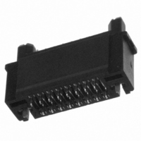
This section provides an outline of the recommended plug cable over-molding practices
for the 45339 and 45593 plug connector modules. The 45339 connector (a 16-circuit wire
termination version) is shown, below, prior to soldering. Please note the following features:
Latch soldertails (2 places)
Figure 5. Soldertail side of the plug connector
Pre-tinned wires should be terminated to the appropriate solder tails working in sequence
and one row at a time, taking care that the insulation does not become exposed more than
1mm from the end of the terminals. The completed assembly after soldering of the wires is
shown below. Dressing of the wires should be avoided until after the soldering and
encapsulation processes are complete.
ECR/ECN INFORMATION:
EC No:
DATE:
Plug Cable Over-Molding
Wire Soldering
6/24/04
UCP2004-2588
APPLICATION SPECIFICATION
PRELIMINARY HANDYLINK™
TITLE:
CREATED / REVISED BY:
T. Gregori/ M. Simmel
Cavities under the latches (2 places)
HANDYLINK™I/O CONNECTOR SYSTEM
APPLICATION SPECIFICATION
Wire soldertails (2 rows)
Marc Simmel
CHECKED BY:
TEMPLATE FILENAME: PRODUCT_SPEC[SIZE_A](V.1).DOC
Figure 6.
Plug Soldering Set-Up
NOTE: The wire bundle
must be properly supported
or clamped as shown,
during soldering and
handling, to avoid
dislodging terminals or
latches from the housing
prior to encapsulation,
application of a strain relief,
and the final over-mold.
APPROVED BY:
Joe Comerci
SHEET No.
11
of
21
Related parts for 45593-1600
Image
Part Number
Description
Manufacturer
Datasheet
Request
R

Part Number:
Description:
Header Connector,PCB Mount,RECEPT,2 Contacts,PIN,0.031 Pitch,PC TAIL Terminal,LOCKING
Manufacturer:
Molex Inc
Part Number:
Description:
Header Connector,PCB Mount,RECEPT,8 Contacts,PIN,0.031 Pitch,PC TAIL Terminal,LOCKING
Manufacturer:
Molex Inc

Part Number:
Description:
Header Connector,PCB Mount,RECEPT,9 Contacts,PIN,0.031 Pitch,PC TAIL Terminal,LOCKING
Manufacturer:
Molex Inc
Part Number:
Description:
Header Connector,PCB Mount,RECEPT,10 Contacts,PIN,0.031 Pitch,PC TAIL Terminal,LOCKING
Manufacturer:
Molex Inc
Part Number:
Description:
Header Connector,PCB Mount,RECEPT,15 Contacts,PIN,0.031 Pitch,PC TAIL Terminal,LOCKING
Manufacturer:
Molex Inc
