4303.2401 Schurter Inc, 4303.2401 Datasheet - Page 5
4303.2401
Manufacturer Part Number
4303.2401
Description
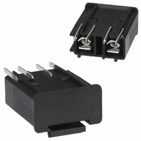
FUSE DRAWER FOR PWR ENTRY MODULE
Manufacturer
Schurter Inc
Series
KD Bowdencabler
Type
Fuse Drawerr
Specifications of 4303.2401
Accessory Type
Fuse Drawer
Product
Holder
Voltage Rating
250 V
Mounting Style
Snap In
Number Of Poles
Two
Current Rating
10 Amps
Termination Style
Quick Connect
Fuse Size
5 x 20 mm
Primary Type
Fuse Drawers
Product Type
Fingergrip and Extra-Safe
Svhc
No SVHC (15-Dec-2010)
Colour
Black
Voltage Rating Vac
250V
Fuse Size Held
5x20
Terminal Type
4.8mm X 0.8mm
Rohs Compliant
Yes
Lead Free Status / RoHS Status
Lead free / RoHS Compliant
For Use With/related Products
KD-Bowdencable
For Use With
KD14.4199.105 - MOD PWR ENTRY 2POLE QC 1.5MM PNLKD14.4199.151 - MOD PWR ENTRY 2POLE QC SCREW PNLKD14.4199.107 - MOD PWR ENTRY 2POLE QC 2.0MM PNLKD14.4199.109 - MOD PWR ENTRY 2POLE QC 2.5MM PNLKD11.4199.151 - MOD PWR ENTRY 1POLE QC SCREW PNLKD11.4199.109 - MOD PWR ENTRY 1POLE QC 2.5MM PNLKD11.4199.105 - MOD PWR ENTRY 1POLE QC 1.5MM PNLKD11.4199.107 - MOD PWR ENTRY 1POLE QC 2.0MM PNL486-1046 - MODULE PWR ENTRY W/SW SCREW-ON
Lead Free Status / Rohs Status
Lead free / RoHS Compliant
Other names
486-1042


5
BOWDEN CABLE
for type KD/KG, CD/CG
Order details and description
How to specify length of
Bowden cable:
R Mounting parallel to direction of actuation
B1 Actuating part
B2 Power entry module
Dimensions in mm (center of mounting hole [B1], outer surface to
center of mounting hole [B2], outer surface)
R
S
B1
B2
Dimensions in mm (center of mounting hole [B1], outer surface to
center of mounting hole [B2], outer surface)
S
Ordering example
The following 3 positions are necessary to place an order:
1. Order No.
2. Order No.
3. Bowden cable
* The Order No. for a customer specific Bowden cable you’ll get
with the acknowledgment.
Delivery time for a customer specific
Bowden cable sample approx. 2 weeks.
Standard Bowden cable sample,
Order No. 0886.0101, ex stock
Type R
Bowden cable assembly instruction
Drop Bowden barrel into seat of switch
socket
fuse drawer
(type of mounting /
dimensions in mm)
[www.schurter.com]
Mounting 90° to direction of actuation
Actuating part
Power entry module
a /
a /
KD14.4199.151
4303.2024.03
*R a/200 b/180 c/40
b /
b /
Type S
Slide clamp around cable
c /
c /
Remote Actuator Technology
The remote actuator cable assembly consists of a wire cable inside
of a plastic insulated spiral wire casing.
Identifying a proper routing of the cable assembly is important. De-
viations from line to line placement will require bends in the cable
with resulting losses in the overall assembly. These inefficiencies
show up as friction losses and lost motion.
Frictional losses are increases in actuation force due to losses in the
assembly. Lost motion is an undesirable difference between the in-
put end of the assembly and the output end.
The principle element of lost motion is backlash and deflection.
Backlash is caused by the wire cable moving inside the casing with
the change in direction of motion. It is the function of clearance bet-
ween the wire cable and casing, plus the number of degrees of
bend in the cable assembly. Deflection of the cable assembly, while
usually low, can be minimized by anchoring the casing.
This is especially true in those applications of cable assemblies with
long lengths and/or large degrees of bend in the system.
All of these losses and resulting inefficiencies can be reduced by the
equipment designer through minimizing the total degress of bend in
the assembly. Because of the number of variables effecting proper
operation of any remotely actuated switch assembly, it is important
that the ordering instructions be used to determine proper cable
length and to provide samples for customer approval.
Consult figure for minimum information required to describe cable
assembly application.
Bowden cable locked into assembly
Degrees of bend in assembly
Related parts for 4303.2401
Image
Part Number
Description
Manufacturer
Datasheet
Request
R

Part Number:
Description:
MSM22 RI SF 10 A 250VAC GN
Manufacturer:
Schurter Inc
Datasheet:
Part Number:
Description:
LSH-Taster 6x6mm / 7,00mm-Blistergurt, taped and reeled
Manufacturer:
Schurter Inc
Part Number:
Description:
Fuse Drawer Quick Connect Snap-In
Manufacturer:
Schurter Inc
Datasheet:
Part Number:
Description:
Power Entry Module Filtered M 3 POS 250VAC 1A Switch/Fuse ST 1 Port
Manufacturer:
Schurter Inc
Datasheet:
Part Number:
Description:
Power Entry Module Filtered M 3 POS 250VAC 10A Switch/Fuse ST 1 Port
Manufacturer:
Schurter Inc
Datasheet:
Part Number:
Description:
Power Entry Module Filtered M 3 POS 250VAC 4A Switch/Fuse ST 1 Port
Manufacturer:
Schurter Inc
Datasheet:
Part Number:
Description:
Power Entry Module Filtered M 3 POS 250VAC 2A Switch/Fuse ST 1 Port
Manufacturer:
Schurter Inc
Datasheet:
Part Number:
Description:
6765 POWER ENTRY MODUL 10A 70C
Manufacturer:
Schurter Inc
Datasheet:
Part Number:
Description:
0102 APPLIANCE OUTLET FOR CABLE 10A 155
Manufacturer:
Schurter Inc