GSF1.2202.31 Schurter Inc, GSF1.2202.31 Datasheet
GSF1.2202.31
Manufacturer Part Number
GSF1.2202.31
Description
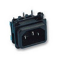
MOD PWR ENT STD PCB 1.5 PNL
Manufacturer
Schurter Inc
Series
GSF1r
Specifications of GSF1.2202.31
Connector Type
Receptacle, Male Pins - Module
Connector Style
IEC 320-C14
Number Of Positions
3
Current
10A
Voltage
250V
Mounting Type
Panel Mount, Snap-In; Through Hole, Right Angle
Termination Style
Solder
Fuse Drawer
Drawer Not Required
Features
Fuse Holder
Gender
Plug
Voltage Rating
250VAC
Current Rating
10A
Connector Mounting
Panel
Contact Termination
Through Hole
Svhc
No SVHC (15-Dec-2010)
Colour
Black
Filtered
No
Filter Type
IEC Inlet Filters
Product
Accessories
Housing Material
Thermoplastic
Mounting Style
Panel
Operating Temperature Range
- 25 C to + 70 C
Lead Free Status / RoHS Status
Lead free / RoHS Compliant
Lead Free Status / RoHS Status
Lead free / RoHS Compliant, Lead free / RoHS Compliant


G G S S F F 1 1
IEC Appliance Connector C14 with Fuseholder 1- or 2-pole
D D e e s s c c r r i i p p t t i i o o n n
- Panel Mount:
- 2 Functions:
- For PCB mounting
- Pick and place version
T T e e c c h h n n i i c c a a l l D D a a t t a a
Ratings IEC
Ratings UL/CSA
Dielectric Strength
Allowable Operation Temp.
Degree of Protection
Protection Class
Terminal
Panel Thickness s
Material: Housing
D D i i m m e e n n s s i i o o n n s s
1
Sandwich/rear-side
Inlet Protection class I, with or without Fuseholder for fuse-links
5 x 20 mm on the rear-side 1- or 2-pole
70° C
C14
www.schurter.com
29.9
34
10 A / 250 VAC; 50 Hz
10 A / 250 VAC; 60 Hz
> 3 kVAC between L-N
> 4 kVAC between L/N-PE
(1 min/50 Hz)
-25 °C to 70 °C
from front side IP 40 acc. to IEC 60529
Suitable for appliances with protection
class I acc. to IEC 61140
For PCB mounting
Snap-in: 1.5/2/2.5/3 mm
Thermoplastic, black, UL 94V-0
Length
rear-side mounting: without groove
A = 6 mm for standard versions
A = 5 mm for pick and place versions
POWER ENTRY MODULES WITHOUT LINE FILTER
Pick & Place Version
19.3
15.9
11.5
1.5
A S
6
34 mm
with insulation cover
C C h h a a r r a a c c t t e e r r i i s s t t i i c c s s
- PCB mount with snap-in or screw-on feet
- All single elements are already wired
- Fuseholder on the inside of the equipment prevents accidental use of
- With or without rear-side insulation cover
- Qualified for use in equipment according IEC/EN 60950
O O t t h h e e r r v v e e r r s s i i o o n n s s o o n n r r e e q q u u e e s s t t
- Ground terminal with quick-connect terminal 6,3 x 0,8 mm
- For protection class II
W W e e b b l l i i n n k k s s
Approvals:
RoHS:
Appliance-Inlet /-Outlet
Fuseholder
Rated Power Acceptance @ Ta
23 °C
Power Acceptance @ Ta > 23°C Admissible power acceptance at higher
Suitable for automatic PCB assembling
incorrect fuse-links by the user
Blister tray meets ESD requirements
http://www.schurter.com/rohs
http://www.schurter.com/approvals
26.8
C14 acc. to IEC/EN 60320-1,
UL 498, CSA C22.2 no. 42 (for cold con-
dition) pin-temperature 70 °C, 10 A, Pro-
tection class I
optional, 1 or 2 pole, Shocksafe category
PC2 acc. to IEC 60127-6,
for fuse-links 5 x 20 mm
5 x 20: 3.15 W (1 pole)/ 2.5 W (2-pole) per
pole
ambient temperature see derating curves
for mounting from rear-side
max. R4.5
30.3
±0.1
Related parts for GSF1.2202.31
Image
Part Number
Description
Manufacturer
Datasheet
Request
R

Part Number:
Description:
MSM22 RI SF 10 A 250VAC GN
Manufacturer:
Schurter Inc
Datasheet:
Part Number:
Description:
LSH-Taster 6x6mm / 7,00mm-Blistergurt, taped and reeled
Manufacturer:
Schurter Inc
Part Number:
Description:
Fuse Drawer Quick Connect Snap-In
Manufacturer:
Schurter Inc
Datasheet:
Part Number:
Description:
Power Entry Module Filtered M 3 POS 250VAC 1A Switch/Fuse ST 1 Port
Manufacturer:
Schurter Inc
Datasheet:
Part Number:
Description:
Power Entry Module Filtered M 3 POS 250VAC 10A Switch/Fuse ST 1 Port
Manufacturer:
Schurter Inc
Datasheet:
Part Number:
Description:
Power Entry Module Filtered M 3 POS 250VAC 4A Switch/Fuse ST 1 Port
Manufacturer:
Schurter Inc
Datasheet:
Part Number:
Description:
Power Entry Module Filtered M 3 POS 250VAC 2A Switch/Fuse ST 1 Port
Manufacturer:
Schurter Inc
Datasheet:
Part Number:
Description:
6765 POWER ENTRY MODUL 10A 70C
Manufacturer:
Schurter Inc
Datasheet:
Part Number:
Description:
0102 APPLIANCE OUTLET FOR CABLE 10A 155
Manufacturer:
Schurter Inc
GSF1.2202.31 Summary of contents
Page 1
IEC Appliance Connector C14 with Fuseholder 1- or 2-pole C14 70° ...
Page 2
for standard versions for pick and place versions ...
Page 3
... GSF1.1202.41 straight - GSF1.1201.41 angled to pin axis - GSF1.1202.51 straight - GSF1.1201.51 angled to pin axis - GSF1.1202.61 straight - GSF1.1201.61 angled to pin axis - GSF1.2202.31 straight - GSF1.2201.31 angled to pin axis - GSF1.2202.41 straight - GSF1.2201.41 angled to pin axis - GSF1.2202.51 straight - GSF1.2201.51 angled to pin axis - GSF1.2202.61 straight - GSF1 ...
Page 4
...