DMS-20PC-0/5-5RS-C Murata Power Solutions Inc, DMS-20PC-0/5-5RS-C Datasheet - Page 2
DMS-20PC-0/5-5RS-C
Manufacturer Part Number
DMS-20PC-0/5-5RS-C
Description
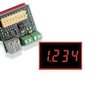
0-5V Red LED 5V-Power 3.5 Dig
Manufacturer
Murata Power Solutions Inc
Datasheet
1.DMS-20PC-05-24RL-C.pdf
(4 pages)
Specifications of DMS-20PC-0/5-5RS-C
Display Type
3 - 1/2 Digit LED
Lead Free Status / RoHS Status
Lead free / RoHS Compliant


Performance/Functional Specifi cations
Typical at T
➀ The DMS-20PC-0/5 can also be used in most 0-10V applications. See the section
➁ INPUT LO (TB1 "–LO") is internally connected to the power return (TB2 "–V").
Inputs
Full Scale Input Range ➀
Input Impedence
Overvoltage Protection ➁
Performance
Sampling Rate
Accuracy (1 minute warm-up):
Temperature Drift (0 to +60°C)
Power Supply Requirements
DMS-20PC-0/5-5RS (90mA max.)
DMS-20PC-0/5-5GS, -5BS (120mA max.) +4.75
DMS-20PC-0/5-5RL 15mA max.)
DMS-20PC-0/5-5RH (90mA max.)
DMS-20PC-0/5-24RL (15mA max.)
Display
Display Type and Size
Polarity Indication
Overrange Indication
Physical/Environmental
Operating Temperature
Storage Temperature
Humidity (non-condensing)
Case Material
Weight
Ordering Information
on 0-10V inputs for more information. See Note 3 on Table 1.
Overvoltage specifi cations apply to the INPUT HI (TB1 "+HI") connection.
DMS-20PC-0/5-5RS-C +5V supply, standard-intensity red LED's
DMS-20PC-0/5-5GS-C +5V supply, standard-intensity green LED's
DMS-20PC-0/5-5BS-C +5V supply, bright blue LED's
DMS-20PC-0/5-5RL-C +5V supply, low-power red LED's
DMS-20PC-0/5-5RH-C +5V supply, high-intensity red LED's
DMS-20PC-0/5-24RL-C +5V to +40V supply, low-power red LED's
DMS-20-CP
Note: A DMS-BZL4 bezel assembly with a sealing gasket is supplied with each meter.
A
= +25°C, unless otherwise noted.
Panel cutout punch
+4.75
+4.75
+4.75
+4.75
Min.
–20
100
4.9
–
–
0
0
3½ digit, 0.37"/9.4mm high LED
"–1_ _ _" for negative inputs
"1_ _ _ " for positive inputs
2.5 reading per second
0.6 ounces (17 grams)
±0.05%FS ±1 Count
"–" for negative V
±0.15
+5.00
+5.00
+5.00
+5.00
Typ.
5.0
Polycarbonate
–
–
–
–
–
–
+5.25
+5.25
+5.25
+5.25
+40.0
Max.
±0.3
140
±40
+60
+75
5.1
95
IN
www.murata-ps.com/dpm
Volts
Volts
Volts
Volts
Volts
Cnts/°C
Units
Volts
Volts
kΩ
°C
°C
%
1. Input Confi guration: The DMS-20PC-0/5 has its input low terminal
2. Panel Mounting: In most standard through-the-panel installations,
TECHNICAL NOTES
OPERATING AND SETUP INSTRUCTIONS
As shipped, the DMS-20PC-0/5 is factory calibrated to read "000" for
a 0.0V input and "1999" for a 5.0V input. The following worst-case
procedure assumes the DMS-20PC-0/5 is completely mis-adjusted, i.e.,
both potentiometers and the DIP switches are randomly set.
1. Set R7 (full scale span/gain adjust) and R3 (zero/offset adjust) fully
2. Select DIP switch setting #1 in Table 1.
3. Apply a precision 0.0V input and adjust R3 until the meter's display
4. Apply a precision 5.0V input and adjust R7 until the meter's display
5. Select the appropriate decimal point by setting SW6, SW7 or SW8 to
(TB1 "LO") internally connected to the power supply ground terminal
(TB2 "–V"). This connection effectively places the meter's input in a
single-ended confi guration. In some applications, single-ended inputs
can cause ground-loop induced errors (the meter's display becomes
unstable or bounces). This occurs because the LED drive currents
fl ow through both the –V terminal and the signal LO terminal.
If suspected ground-loop errors are encountered, and the input signal
LO terminal is externally connected to –V somewhere else in the
system, try removing the connection to TB1 "LO". Inputs which have
no ground-return connection to –V (commonly referred to as "fl oating
inputs") must have their most negative potential tied to TB1 "LO".
Please consult DATEL for more information.
Applications which require electrical isolation between the input
signal source and the system power supply must use a separate
transformer-isolated supply to power the meter.
the DMS-20PC-0/5 must be secured to the panel with DMS-BZL4
bezel assemblies (see the Mechanical Specifi cations section for more
information).
clockwise, roughly 22 turns, and place SW1-SW8 to OFF (down
position).
reads "000".
reads "1999". Repeat steps 3 and 4 to make sure the adjustments
do not affect one another.
ON (DP1, DP2 or DP3 respectively).
NOTE: The "000" to "1999" display readings referred to in the
instructions above are for illustrative purposes only. If other display
readings such as "000" to "1200" are desired, refer to the DIP-
Switch Settings Tables for SW1-SW4 settings. (SW5 is reserved for
future use, it has no affect on display operation.) The initial setting
of R3 and R7 fully clockwise is recommended in the adjustment
procedure for all the following examples.
DMS-20PC-0/5 Series
0-5V and 0-10V Input 3½ Digit, LED
08 Jan 2010 MPM_DMS20pc_5V.B06 Page 2 of 4
Display Process Control Monitors
email: sales@murata-ps.com
Related parts for DMS-20PC-0/5-5RS-C
Image
Part Number
Description
Manufacturer
Datasheet
Request
R

Part Number:
Description:
0-5V Red LED 5V-Power 3.5 Dig
Manufacturer:
Murata Power Solutions Inc
Datasheet:
Part Number:
Description:
0-5V Red LED 5V-Power 3.5 Dig
Manufacturer:
Murata Power Solutions Inc
Datasheet:

Part Number:
Description:
Voltage Meter
Manufacturer:
Murata Power Solutions Inc
Datasheet:

Part Number:
Description:
DPM ±200mV 3.5 Dig Green LED
Manufacturer:
Murata Power Solutions Inc
Datasheet:

Part Number:
Description:
DATEL PANEL METERS
Manufacturer:
Murata Power Solutions Inc
Datasheet:
Part Number:
Description:
DPM ±200mV 3.5 Dig Red LED
Manufacturer:
Murata Power Solutions Inc
Datasheet:
Part Number:
Description:
DPM ±200mV 3.5 Dig Red LED
Manufacturer:
Murata Power Solutions Inc
Datasheet:
Part Number:
Description:
DPM ±200mV 3.5 Dig Yel. LED
Manufacturer:
Murata Power Solutions Inc
Datasheet:

Part Number:
Description:
POWER OVER ETHERNET MODULE
Manufacturer:
Murata Power Solutions Inc
Datasheet:

Part Number:
Description:
POWER OVER ETHERNET MODULE
Manufacturer:
Murata Power Solutions Inc
Datasheet:

Part Number:
Description:
Digital Panel Meters DMS-20 BezelAssembly Panel mount
Manufacturer:
Murata Power Solutions Inc
Datasheet:

Part Number:
Description:
DPM LED MINI 2VDC 3.5DIG LP RED
Manufacturer:
Murata Power Solutions Inc
Datasheet:

Part Number:
Description:
DPM LED 2VDC 4.5DIGIT GREEN
Manufacturer:
Murata Power Solutions Inc
Datasheet:

Part Number:
Description:
DPM LED 2VDC 3.5DIGIT LP RED
Manufacturer:
Murata Power Solutions Inc
Datasheet:

Part Number:
Description:
Transformers 5Vin 5Vout 200mA 4000Vdc 1:1.33 turn
Manufacturer:
Murata Power Solutions Inc
Datasheet: