DSD-40BCD-GS-C Murata Power Solutions Inc, DSD-40BCD-GS-C Datasheet - Page 3
DSD-40BCD-GS-C
Manufacturer Part Number
DSD-40BCD-GS-C
Description
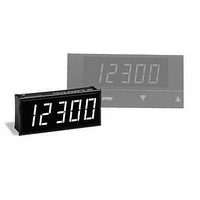
Slave Display 4.5 Dig Grn LED
Manufacturer
Murata Power Solutions Inc
Type
One-Piece LED Displaysr
Datasheet
1.DSD-40BCD-RS-C.pdf
(5 pages)
Specifications of DSD-40BCD-GS-C
Equipment Type
One-Piece LED Displays
Display Type
4 - 1/2 Digit LED
Lead Free Status / RoHS Status
Lead free / RoHS Compliant
Available stocks
Company
Part Number
Manufacturer
Quantity
Price


3. Decimal Point Inputs (DP1-DP4, Pins 4-6, 8): The four, active-low,
4. POLARITY (Pin F): The function of this active-low pin is to turn on
5. Controlling Display Brightness: The LED current-setting compo-
6. Highlighting Selected Digits: In many instrument designs, it is
sequence can be used, as long as BCD data is presented at the cor-
rect corresponding DIGIT DRIVE interval. An important point to keep
in mind is that the DSD-40BCD has no internal data latches! The
DIGIT DRIVE and BCD data inputs must be continuously strobed to
keep the display properly illuminated.
decimal point segments are multiplexed in a similar, though not
identical, manner as the rest of the digit segments. The four decimal
points are controlled by their respective DIGIT DRIVE inputs. A selected
decimal point may be permanently connected to ground. It will only be
illuminated when its respective DIGIT DRIVE input is high. For example,
if pin 6 (DP1) is hard-wired to pin 3 (5V RETURN), DP1 will only be on
during the time interval that DIGIT DRIVE 1 is high.
As the specifi cations table clearly states, DP1-DP4 each require 20mA
of sink current in order to achieve good illumination levels. Unused
decimal points may be left open. The specifi ed minimum V
only if logic-level devices are used to select the decimal points.
the minus sign if negative readings are desired. The polarity input,
like the decimal points, can also be permanently connected to ground.
However, POLARITY is logic-level compatible and does not require the
high sink currents that DP1-DP4 do. If negative readings are never
displayed, the POLARITY input may be left open.
nents inside the DSD-40BCD are selected to produce good display
brightness — while keeping power dissipation at reasonable levels
— with a 20% duty cycle. Since no data latches are utilized in the
DSD-40BCD design, the user can exercise full control over how many
digits are enabled, and their relative brightness, by manipulating the
duty cycle of the DIGIT DRIVE input.
To turn off one digit, for a four digit application, simply leave the
respective DIGIT DRIVE input (DIGIT DRIVE 5 in this example) open
or low. If the timing relationships remain unchanged (i.e., 20% duty
cycle), the display brightness will remain the same as when all fi ve
digits are used. However, if the duty cycle is changed to 25% (because
only four digits are used), the increase in display intensity will be
noticeable. In most applications, this increase in intensity will not be
signifi cant enough to justify any timing changes.
sometimes desirable to highlight or "fl ash" one particular digit to draw
the user's attention to that digit. Once again, duty cycle control of
the digit drive inputs makes this a relatively simple task. The easiest
way is to fl ash the digit on and off, at a 0.5 to 1Hz rate, with the DIGIT
DRIVE input. Keeping the duty cycle fi xed at 20% for 5-digit applica-
tions, and 25% for 4-digits, will keep the intensity of the non-fl ashed
digits uniform.
IH
www.murata-ps.com/dpm
applies
7. Power Supply Decoupling: The DSD-40BCD is not sensitive to logic
8. Interfacing BCD-Output A/D Converters: The DSD-40BCD accepts
9. DISPLAY TEST (Pin 2): The DSD-40BCD's display can have all its
10. Soldering Methods: DSD-40BCD Series displays easily withstand
11. Suggested Mating Connectors:
Miniature 4½ Digit, BCD Input, Slave LED Display
noise or spikes, on either the 5V supply or the data inputs, because
it does not use any edge-triggered logic. However, it does generate a
fair amount of switching transients due to the display's multiplexed
architecture. A tantalum electrolytic capacitor, in the range of 15 to
22μF, in parallel with a 0.1μF ceramic capacitor will reduce the LED
switching transients. These two capacitors should be located as close
as possible to pins 1 and 3.
the BCD data from DATEL's DMS-40PC-X-RS-BCD Series, 4½ Digit
Panel Meters. DMS-40PC meters are exactly the same size as the
DSD-40BCD display making it ideal for use in remote-display applica-
tions.
The DSD-40BCD will also interface directly with the ICL7135, 4½ digit,
integrating A/D converter's BCD and DIGIT DRIVE outputs. The only
difference is that the ICL7135 has its fi ve DIGIT DRIVE outputs labeled
in a right-to-left order, i.e., the 7135's MSD is labeled digit 5 and its
LSD is labeled digit 1. This is opposite to the DSD-40BCD labeling its
MSD digit 1 and its LSD digit 5. Please refer to the 7135's data sheet
for more information.
segments enabled by bringing DISPLAY TEST low. The display will
show "–18888" (excluding the decimal points) as long as the digit
drive inputs are continuously strobed.
most common manual and wave soldering operations. However, we
highly recommend that you evaluate the effects your particular solder-
ing techniques may have on the display's polycarbonate case and
overall performance. We also recommend the use of no-clean solders
since their residue normally has no detrimental effects on low-speed
digital devices.
Board mounted:
Panel mounted: DATEL recommends the use of IDC (insulation
displacement) connectors when panel mounting the DSD-40BCD.
SAMTEC's HCS series of IDC cable strips can be ordered in a variety of
lengths and connector terminations. Please contact SAMTEC, Inc. at:
USA (Indiana)
Europe (Scotland) 01236-739292
Asia (Singapore)
Socket
812-944-6733
65-745-5955
DSD-40BCD Series
10 Jan 2011 MPM_DSD-40BCD.B02 Page 3 of 5
DATEL P/N 4320-01074-0
email: sales@murata-ps.com
Fax: 812-948-5047
Fax: 01236-727113
Fax: 65-841-1502
Related parts for DSD-40BCD-GS-C
Image
Part Number
Description
Manufacturer
Datasheet
Request
R

Part Number:
Description:
Slave Display 4.5 Dig Red LED
Manufacturer:
Murata Power Solutions Inc
Datasheet:

Part Number:
Description:
Slave LED Display
Manufacturer:
Murata Power Solutions Inc
Datasheet:

Part Number:
Description:
POWER OVER ETHERNET MODULE
Manufacturer:
Murata Power Solutions Inc
Datasheet:

Part Number:
Description:
POWER OVER ETHERNET MODULE
Manufacturer:
Murata Power Solutions Inc
Datasheet:

Part Number:
Description:
POWER OVER ETHERNET MODULE
Manufacturer:
Murata Power Solutions Inc
Datasheet:

Part Number:
Description:
POWER OVER ETHERNET MODULE
Manufacturer:
Murata Power Solutions Inc
Datasheet:

Part Number:
Description:
Power Inductors 2.2mH1.4A
Manufacturer:
Murata Power Solutions Inc
Datasheet:

Part Number:
Description:
Power Inductors 6.8uH 3.6A 20mOhm Toroidal SMT
Manufacturer:
Murata Power Solutions Inc
Datasheet:

Part Number:
Description:
Power Inductors Radial1.5mH 150mA
Manufacturer:
Murata Power Solutions Inc
Datasheet:
Part Number:
Description:
Power Inductors 680uH 2.2A 1.3MHz Radial PCB Mounting
Manufacturer:
Murata Power Solutions Inc
Datasheet:

Part Number:
Description:
Transformers 5Vin 5Vout 200mA 4000Vdc 1:1.33 turn
Manufacturer:
Murata Power Solutions Inc
Datasheet:

Part Number:
Description:
POWER SUPPLY
Manufacturer:
Murata Power Solutions Inc
Datasheet:

Part Number:
Description:
DPM LED MINI 2VDC 3.5DIG LP RED
Manufacturer:
Murata Power Solutions Inc
Datasheet:

Part Number:
Description:
CONV DC/DC 1W 5VIN 5VOUT SIP SGL
Manufacturer:
Murata Power Solutions Inc
Datasheet:

Part Number:
Description:
CONV DC/DC 1W 5VIN 3.3V SIP SGL
Manufacturer:
Murata Power Solutions Inc
Datasheet: