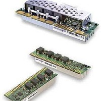
VRM10-80-12-PY Emerson Network Power, VRM10-80-12-PY Datasheet - Page 2

VRM10-80-12-PY
Manufacturer Part Number
VRM10-80-12-PY
Description
11-12.6Vin, 0.8375-1.6000V@80A, 3.19" X 0.77" X 1.24 , 85%Eff, VMR10.0 & 10.1 Specs, RoHS 6
Manufacturer
Emerson Network Power
Datasheet
1.VRM10-85-12-UY.pdf
(10 pages)
Specifications of VRM10-80-12-PY
Output Power
128 W
Input Voltage Range
11 V to 12.6 V
Input Voltage (nominal)
12 V
Number Of Outputs
1
Output Voltage (channel 1)
0.8375 V to 1.6 V
Output Current (channel 1)
80 A
Package / Case Size
93.35 mm x 29.46 mm x 25.4 mm
Output Voltage
0.8375 V to 1.6 V
Lead Free Status / Rohs Status
Lead free / RoHS Compliant
Specifications
Unless otherwise stated, all specifications are typical at nominal input, maximum
continuous rated load at 25 °C and voltages are referenced to Vin-.
OUTPUT SPECIFICATIONS
Voltage adjustability
Output current (Iout)
VRM10-85-12-UY
VRM10-80-12-PY
VRM10-105-12-EJ
Load line (LL) adjustability
(See LL codes, Table 1)
Output voltage (Vout)
(Vo sen+ minus Vo sen-)
(See Notes 3, B)
Ripple and noise
(See Notes 1, 2)
Short circuit protection
Remote sensing compensating voltage
INPUT SPECIFICATIONS
Input voltage range
Input current
VRM10-85-12-UY
VRM10-80-12-PY
VRM10-105-12-EJ
No load
OUTEN OFF
UVLO turn ON voltage
UVLO turn OFF voltage
Hysteresis
Start-up time
(using OUTEN)
(See VID codes,Table 3)
Continuous
Peak non-sustained
Continuous
Peak non-sustained
Continuous
Peak non-sustained
Vo max
Vo min VID - Rout * Iout - 0.040V (-U/-E)
Vo min
Where
Rout
Iout
20 MHz bandwidth
12 Vin nominal
11Vin, VID=1.325 V, Iout=100 A
11Vin, VID=1.400 V, Iout=91 A
11VIN, VID=1.325V, Iout=120 A
0 ºC <tamb <60 ºC
0 ºC <tamb <60 ºC
11.0 V < Vin <12.6 V
(PWRGD transitioning high
VID = programmed voltage (V)
VID - Rout * Iout - 0.038V (-P)
brickwall automatic recovery
25 0 mA typ., 300 mA max.
Continuous current limit,
Fixed or programmable
output impedance (W)
Up to 300 mV max.
Output current (A)
VID - Rout * Iout V
0.8375-1.6000 Vdc
0.91-1.25 mW
8.7 V ± 4.5%
9.5 V ± 2.6%
50 mA max.
8 mV pk-pk
11.0-12.6 Vdc
100 A max.
120 A max.
105 A max.
85 A max.
80 A max.
91 A max.
0.8 V typ
10 ms max.
0 A min.
15.3 A
14.2 A
18.5 A
INPUT SPECIFICATIONS CONTD.
OUTEN, VID and LL signal valid states:
ON or Logic ‘1’
OFF or Logic ‘0’
GENERAL CHARACTERISTICS
Efficiency
Switching frequency
Fixed (See Note 4)
Approvals and standards (See Note 5)
Material flammability
Weight
1 05 A
MTBF
Telecordia SR-332
Mating connector
1 05 A
Connector fingers
ENVIRONMENTAL SPECIFICATIONS
Temperature shock
non-operating
Humidity
(Non-condensing)
Altitude
s torage
Shock
n on-operational
Vibration
(See Note 6)
Thermal performance
(See Note 7)
Storage temperature
See table 2 on page 2
80 A/85 A
105 A
80 A/85 A
70 g (2.47 oz)
80 A/85 A
105 A
80 A/85 A
See Figure 8
Operating
20 °C/hour
Operating
storage
Operating
50,000 feet max.
Operational and
Half sine wave
Operational and
non-operational
Operating ambient
temperature
(Non-condensing)
Embedded Power for
Business-Critical Continuity
-0.3 Vdc min., 0.4 Vdc max.
0.8 Vdc min., 5.5 Vdc max.
Gold plated, 30 µ-inches
IEC/EN60950 VDE
-40 °C to + 100 °C
10,000 feet max.
2,000,000 hours
1,648,000 hours
0.02 G
VID = 1.325 V
38 g (1.34 oz)
0 °C to +60 °C
See Figure 7
10 °C/hour
30 G 11ms
2
/Hz max.
UL94V-0
2.2 MHz
1.1 MHz
85% RH
95% RH
Rev.07.20.07
vrm10 series
2 of 10


