A11-B0-34-450-131-E Carling Technologies, A11-B0-34-450-131-E Datasheet - Page 5
A11-B0-34-450-131-E
Manufacturer Part Number
A11-B0-34-450-131-E
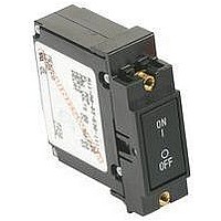
Description
CIRCUIT BREAKER, HYD-MAG, 1P, 277V, 5A
Manufacturer
Carling Technologies
Series
Ar
Datasheet
1.AC1-B0-34-610-1G1-C.pdf
(23 pages)
Specifications of A11-B0-34-450-131-E
Input Voltage Vac
277V
No. Of Poles
1
Current Rating
5A
Interrupting Capacity
5kA
Dielectric Strength
3.75kV
Trip Time
20s
Voltage Rating Vdc
80V
Trip Time Max
20 Sec
Product Type
Circuit Breakers
Voltage Rating
277 VoltsAC, 80 VoltsDC
Number Of Poles
1 Pole
Mounting Style
Screw
Actuator Type
Rocker
Termination Style
Screw
Circuit Function
Series Trip (Current)
Color
White
Features
A rockerguard and push-to-reset bezel help prevent inadvertent actuation
Illuminated
No
Length
50.8 mm
Product
Hydraulic Magnetic Circuit Breakers
Width
19.18 mm
Mounting Type
Push-On
Rohs Compliant
Yes
Lead Free Status / RoHS Status
Lead free / RoHS Compliant
Lead Free Status / RoHS Status
Lead free / RoHS Compliant


38
A-Series Handle UL Recognized – Ordering Scheme
Notes:
1
2
3
4
5
6
7
8
9
10
11
12
13
14
15
1
Series
A
1 SERIES
A
2 ACTUATOR
A
B
S
T
3 POLES
1
2
4 CIRCUIT
A
B
C
D
E
5 AUXILIARY/ALARM SWITCH
0
1
2
3
4
6 FREQUENCY & DELAY
03
10
11
12
14
16
20
21
22
24
26
3
2
3
6
6
Actuator Code:
A: Handle tie pin spacer(s) and retainers provided unassembled with multi-pole units.
B: Handle location as viewed from front of breaker:
S: Handle moves to mid-position only upon electrical trip of the breaker. Available with cir-
cuit codes B, C, D, E, F, G, H and K.
T: Handle moves to mid-position and alarm switch activates only upon electrical trip of the
breaker. Available with circuit codes B & C.
Switch Only circuits, rated up to 50 amps and 6 poles, and only available with VDE
Certification when tied to a protected pole (Circuit Code B, C, D or H.), For .02 to 30 amps,
select Current Code 630. For 35 - 50 amps, select Current Code 650.
Available with terminal Codes 1, 2 and 3. Current Rating limited to 30 amps maximum.
Consult factory for available Dual Coil options, as special catalog number is required. With
Shunt construction, Dual Coils will trip instantaneously on line voltage. Dual coils require
30VA minimum power to trip and are rated for intermittent duty only.
Auxiliary Switch breakers with Series Trip & Switch Only circuits: ≤ 30A - supplied with
standard half shells. 35-50A - supplied with extended boat (B-Style) half shells.
On multi-pole breakers, one auxilary switch is supplied, mounted in the extreme right pole.
Separate pole type voltage coils not rated for continuous duty. Available only with delay
codes 10 and 20.
Available with Circuit Codes B & D only. VDE Certified to 30 amps. UL Recognized, CSA
Accepted & TUV Certified to 50 amps.
VDE Certification available with single pole breakers with DC Delay only. UL Recognition
and CSA Accepted available in one and two pole breakers.
Screw Terminals are recommended on ratings greater than 20 amps. Ratings over 30
amps are only available with Terminal Codes 5, 9, G, H, M and Q..
Terminal Code 1: VDE Certification up to 25 amps and UL Recognition and CSA
Certification up to 30 amps, but not recommended over 20 amps.
Terminal Codes 3, 5, E and H (Bus Type) with VDE, are supplied with Lock Washers, and
Terminal Code M (M6 Threaded Stud) with VDE is supplied with Lock and Flat Washers.
These breakers are only VDE Certified when the washers are used.
Terminal Code L: VDE Certified available up to 12A. UL Recognized & CSA Accepted avail-
able up to 30A.
Single pole breakers with Terminal Code P (Printed Circuit Board) are available up to 30
amps with VDE Certification and 50 amps with UL Recognition and CSA Accepted, with
Circuit Codes A, B and C. Two pole breakers with Terminal Code P (Printed Circuit Board)
are available up to 40 amps with UL Recognition and CSA Accepted with Circuit Codes A,
B and C.
Terminal Code Q not available with VDE certification.
Single pole only.
Handle, one per pole
Handle, one per multipole unit
Mid-Trip Handle, one per pole
Mid-Trip Handle, one per pole & Alarm Switch
Switch Only (No Coil)
Series Trip (Current)
Series Trip (Voltage)
Shunt Trip (Current)
Shunt Trip (Voltage)
w/o Aux Switch
S.P.D.T., 0.093 Q.C. Term.
S.P.D.T., 0.110 Q.C. Term.
S.P.D.T., 0.139 Solder Lug
S.P.D.T., 0.110 Q.C. Term.
(Gold Contacts)
DC 50/60Hz, Switch Only
DC Instantaneous
DC Ultra Short
DC Short
DC Medium
DC Long
50/60Hz Instantaneous
50/60Hz Ultra Short
50/60Hz Short0
50/60Hz Medium
50/60Hz Long
2 pole - left pole
4 pole - two handles at center poles
6 pole - four handles at center poles
One
Two
2
Actuator
A 3
1
3
Poles
3
4
–
5
Three
Four
4
Circuit
3 pole - center pole
5 pole - three handles at center poles
B 0
F
G
H
K
5
6
7
8
9
30
31
32
34
36
42
44
46
52
54
56
3
3,4
3,4
3
7
7
7
7
7
7
5
Aux/Alarm
Switch
Relay Trip (Current)
Relay Trip (Voltage)
Dual Coil with Shunt Trip
Voltage Coil
Dual Coil with Relay Trip
Voltage Coil
S.P.S.T., 0.093 Q.C.
Term.(Gold Contacts)
S.P.S.T., 0.139 Solder Lug
S.P.S.T., 0.110 Q.C.
Term.(Gold Contacts)
S.P.S.T., 0.187 Q.C. Term.
S.P.D.T., 0.187 Q.C. Term.
DC, 50/60Hz Instantaneous
DC, 50/60Hz Ultra Short
DC, 50/60Hz Short
DC, 50/60Hz Medium
DC, 50/60Hz Long
50/60Hz Short, Hi-Inrush
50/60Hz Medium, Hi-Inrush
50/60Hz Long, Hi-Inrush
DC, Short,Hi-Inrush
DC,Medium, Hi-Inrush
DC, Long, Hi-Inrush
5
6
–
Five
Six
6
Frequency
& Delay
10
–
020
025
030
035
040
045
050
055
060
065
070
075
080
085
090
095
210
215
220
A06
A12
A18
A24
8 TERMINAL
1
2
3
4
5
6
7
8
9
B
C
9 ACTUATOR COLOR & LEGEND
Actuator Color
White
Black
Red
Green
Blue
Yellow
Gray
Orange
Black (short handle)
10 MOUNTING/BARRIERS
1
A
2
B
5
6
7
8
11 AGENCY APPROVAL
C
D
E
I
7 CURRENT RATING (AMPERES)
OR VOLTAGE COIL (NOMINAL RATED VOLTAGE)
10
11
11
7
Current Rating
450
UL Recognized & CSA Accepted
VDE Certified, UL Recognized & CSA Accepted
TUV Certified, UL Recognized & CSA Accepted
UL Rec. STD 1077, UL Rec. 1500 (ignition protected), & CSA Accepted
Push-On 0.250 Tab (Q.C.)
Screw 8-32 w/upturned lugs
Screw 8-32 (Bus Type)
Screw 10-32 w/upturned lugs
Screw 10-32 (Bus Type)
Screw 8-32 w/upturned lugs
and 30° bend
Screw 8-32 (Bus Type) and
30° bend
Screw 10-32 w/upturned lugs
and 30° bend
Screw 10-32 (Bus Type) and
30° bend
Screw M5 w/upturned lugs
Screw M4 w/upturned lugs
MOUNTING STYLE
Threaded Inserts, 2 per pole
6-32 x 0.195 inches
6-32 X 0.195 inches
ISO M3 x 5mm
ISO M3 x 5mm (multipole only)
Front panel Snap-In, 0.75” wide bezel
without Handleguard
without Handleguard (multipole only)
Front panel Snap-In, 0.96” wide bezel
without Handleguard, 1-pole 0.96" wide;
multipole units have .105" bezel overhang on all sides
without Handleguard, 1-pole 0.96" wide;
(multipole only) .105" bezel overhang on all sides
12 DC
18 DC
24 DC
0.020
0.025
0.030
0.035
0.040
0.045
0.050
0.055
0.060
0.065
0.070
0.075
0.080
0.085
0.090
0.095
0.100
0.150
0.200
6 DC
9
15
I-O
A
C
F
H
K
M
P
R
T
225
230
235
240
245
250
255
260
265
270
275
280
285
290
295
410
512
415
517
A32
A48
A65
J06
–
32 DC
48 DC
65 DC
8
Terminal
0.250
0.300
0.350
0.400
0.450
0.500
0.550
0.600
0.650
0.700
0.750
0.800
0.850
0.900
0.950
1.000
1.250
1.500
1.750
6 AC
1 B 1
ON-OFF
B
D
G
J
L
N
Q
S
U
9
Actuator
Color
420
522
527
430
435
440
445
450
455
460
465
470
475
480
485
490
495
610
710
J12
J18
J24
J48
E
F
G
H
L
M
Q
R
T
P
S
12
11
Dual
1
2
3
4
5
6
7
8
9
11
13
13
11
14
11
www.carlingtech.com
Screw M4 (Bus Type)
Screw M5 w/upturned lugs
and 30° bend
Screw M5 (Bus Type)
and 30° bend
Screw M5 (Bus Type)
0.250 Q.C./ Solder Lug
M6 Threaded Stud
Push-In Stud
Screw M4 w/upturned lugs
and 30° bend
Screw M4 (Bus Type)
and 30° bend
Printed Circuit Board
Terminals
Push-On 0.110 Tab (Q.C.)
10.000
10.500
12 AC
18 AC
24 AC
48 AC
2.000
2.250
2.750
3.000
3.500
4.000
4.500
5.000
5.500
6.000
6.500
7.000
7.500
8.000
8.500
9.000
9.500
10
Mounting/
Barriers
6
Legend Color
Black
White
White
White
White
Black
Black
Black
White
BARRIERS
no
yes
no
yes
no
yes
no
yes
–
611
711
612
712
613
614
615
616
617
618
620
622
624
625
630
635
640
645
650
J65
K20 120 AC
L40
8
8
8
8
240 AC
11
Agency
Approval
11.000
11.500
12.000
12.500
13.000
14.000
15.000
16.000
17.000
18.000
20.000
22.000
24.000
25.000
30.000
35.000
40.000
45.000
50.000
C
65 AC
Related parts for A11-B0-34-450-131-E
Image
Part Number
Description
Manufacturer
Datasheet
Request
R

Part Number:
Description:
CIRCUIT BREAKER, HYD-MAG, 1P, 277V, 10A
Manufacturer:
Carling Technologies
Datasheet:
Part Number:
Description:
CIRCUIT BREAKER, HYD-MAG, 1P, 277V, 20A
Manufacturer:
Carling Technologies
Datasheet:
Part Number:
Description:
CIRCUIT BREAKER, HYD-MAG, 1P, 277V, 25A
Manufacturer:
Carling Technologies
Datasheet:

Part Number:
Description:
Circuit Breakers 30A 1 POLE .250 QC FLAT ROCKER RED
Manufacturer:
Carling Technologies
Datasheet:
Part Number:
Description:
Circuit Breakers 15A 1 POLE .250 QC FLAT ROCKER RED
Manufacturer:
Carling Technologies
Datasheet:

Part Number:
Description:
Toggle Switches CARLING TECHNOLOGIES
Manufacturer:
Carling Technologies
Datasheet:
Part Number:
Description:
CARLING POWER SWITCH LIGHTED 10 AMP 250 VOLT AC
Manufacturer:
Carling Technologies
Part Number:
Description:
CARLING SWITCH
Manufacturer:
Carling Technologies
Part Number:
Description:
LIGHT INDICATOR GRN 12VDC PNLMNT
Manufacturer:
Carling Technologies
Part Number:
Description:
CONTURA ILL INDICATOR 12V RED
Manufacturer:
Carling Technologies
Part Number:
Description:
Current Regulator Diodes CURRENT REGULATOR DIODES 3.6mA
Manufacturer:
Carling Technologies
Part Number:
Description:
Rocker Switches
Manufacturer:
Carling Technologies
Datasheet: