IEG6-1-72-5.00-01-V AIRPAX, IEG6-1-72-5.00-01-V Datasheet - Page 19
IEG6-1-72-5.00-01-V
Manufacturer Part Number
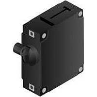
IEG6-1-72-5.00-01-V
Description
CIRCUIT BREAKER, HYD-MAG, 1P, 240V, 5A
Manufacturer
AIRPAX
Series
IEGr
Datasheet
1.IEG6-1-72-10.0-01-V.pdf
(24 pages)
Specifications of IEG6-1-72-5.00-01-V
Input Voltage Vac
240V
No. Of Poles
1
Current Rating
5A
Interrupting Capacity
7.5kA
Dielectric Strength
3.75kV
Trip Time
20s
Voltage Rating Vdc
80V
Leaded Process Compatible
Yes
Rohs Compliant
Yes
Lead Free Status / RoHS Status
Lead free / RoHS Compliant


http://airpax.sensata.com/
Notes:
IDG Supplementary Protectors
CEG Communications Equipment Circuit Breakers
LEG Circuit Breakers
AGENCY APPROVALS
General notes:
All supplementary protectors are of the overcurrent (OC) type
The family of protectors has been evaluated for end use application for use groups (UG) A, B, C and D
The terminals (FW) are suitable for factory wiring only (0)
The maximum voltage ratings for which the protectors have been tested are shown in the chart
The current is the amperage range that the protectors have been tested
The tripping current (TC) for all of the protectors is “1” (in the range of 125% to 135% of ampere rating except for
the 400Hz protectors which is “2” (more than 135% of ampere rating)
The overload rating (OL) - designates whether the protector has been tested for general use or motor starting
applications.
Max Voltage
Max Voltage
Max Voltage
Max Voltage
125 / 250
125 / 250
250 (4)
250 (4)
250 (5)
250 (5)
125/250
120/240
125
125
125
240
240
250
250
250
277
277
250
250
80
125
250
125
48
65
80
(1) With 125 A max. series fuse; (2) With 80 A max. series fuse; (3) With 50 A max. circuit breaker; (4) With blocked vent construction;
(5) Non-standard construction. “Fit for further use” approval
IAG/IUG/IEG Supplementary Protectors
Frequency (Hz)
Frequency (Hz)
Frequency (Hz)
Frequency (Hz)
50/60
50/60
50/60
50/60
50/60
50/60
50/60
50/60
50/60
50/60
50/60
50/60
50/60
50/60
50/60
50/60
50/60
50/60
50/60
50/60
50/60
400
400
DC
DC
DC
DC
Phase
Phase
Phase
Phase
1 & 3
1 & 3
1 & 3
1 & 3
1 & 3
1 & 3
1 & 3
1 & 3
—
—
—
—
1
1
1
1
1
1
1
3
1
1
3
1
1
1
1
Minimum Poles
Minimum Poles
Minimum Poles
Minimum Poles
—
1
1
1
1
2
1
1
1
1
1
1
1
1
2
3
1
1
1
1
1
1
2
1
1
1
2
0 – tested at 1.5 times amp rating for general use
1 – tested at 6 times AC rating or 10 times DC rating for motor starting
The short circuit current rating (SC) – The short circuit rating in amperes following a letter and number designating the
test conditions and any calibration following the short circuit test is defined below:
C – Indicates short circuit test was conducted with series overcurrent protection
U – Indicates short circuit test was conducted without series overcurrent protection
1 – Indicates a recalibration was not conducted as part of the short circuit testing
2 – Indicates a recalibration was performed as part of the short circuit testing
3 – Indicates recalibration was performed along with the dielectric and voltage withstand for “Suitable for Further Use”
rating
2/1 - 30/15
.02 to 50
.02 to 50
.02 to 30
.02 to 50
.02 to 50
.02 to 50
.02 to 50
.02 to 30
.02 to 30
.02 to 30
.02 to 30
.02 to 50
.02 to 50
.02 to 30
.02 to 30
.02 to 30
.02 to 30
UL/CSA
UL/CSA
UL/CSA
UL/CSA
IAG/IUG/IEG/CEG/LEG Series - Delay Curves
.02 to 2
Rated Current (Amps)
.02-50
.02-50
.02-50
.02-50
.02-30
.05-50
.05-30
1-30
.10 to 30
.10 to 50
.10-30
.10-30
TüV
TüV
TüV
TüV
—
—
—
—
—
—
—
—
—
—
—
—
—
—
—
—
—
—
—
—
—
—
—
Short Circuit Rating (SC), Amps
UL1077 & CSA
UL1077 & CSA
C1, 5000(3)
C2, 5000(1)
C2, 5000(1)
C2, 3500(2)
C1, 3500(2)
C2, 5000(2)
U2, 7500
U2, 3000
U3, 1000
U1, 3000
U1, 2000
U2, 5000
U1, 2000
U1, 1000
U3, 1000
U3, 1000
U2, 2000
U2, 1500
U2, 5000
U2, 3000
U2, 2000
U2, 1500
U1, 1000
UL489A
U3, 200
UL489
5000
5000
5000
2000
2000
4000
2000
TüV
—
—
—
—
—
—
—
—
—
—
—
—
—
—
—
—
—
TüV
—
—
—
—
—
TüV
—
TüV
122
Related parts for IEG6-1-72-5.00-01-V
Image
Part Number
Description
Manufacturer
Datasheet
Request
R


Part Number:
Description:
CIRCUIT BREAKER HYMAG SP 50A
Manufacturer:
Sensata Technologies/Airpax
Datasheet:

Part Number:
Description:
CIRCUIT BREAKER, HYD-MAG, 1P, 240V, 10A
Manufacturer:
AIRPAX
Datasheet:
Part Number:
Description:
CIRCUIT BREAKER, HYD-MAG, 1P, 240V, 15A
Manufacturer:
AIRPAX
Datasheet:
Part Number:
Description:
CIRCUIT BREAKER, HYD-MAG, 1P, 240V, 20A
Manufacturer:
AIRPAX
Datasheet: