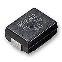
ERZVF2M330 Panasonic, ERZVF2M330 Datasheet - Page 5

ERZVF2M330
Manufacturer Part Number
ERZVF2M330
Description
VARISTOR, SMD, 33V
Manufacturer
Panasonic
Datasheet
1.ERZVF2M101.pdf
(5 pages)
Specifications of ERZVF2M330
125a
Suppressor Type
Ptc Fuse Case
SMD
Clamping Voltage
65V
Peak Energy (10/1000us)
1.2J
Voltage Dc
26V
Voltage Rating Vac
20V
Operating Temperature Range
-40°C To +85°C
Suppressor Type
Absorber
Rohs Compliant
Yes
Peak Surge Current @ 8/20µs
125A
Varistor Case
SMD
Clamping Voltage Vc Max
65V
Voltage Rating Vdc
26V
Lead Free Status / RoHS Status
Lead free / RoHS Compliant
Available stocks
Company
Part Number
Manufacturer
Quantity
Price
Company:
Part Number:
ERZVF2M330
Manufacturer:
YAZAKI
Quantity:
12 000
Company:
Part Number:
ERZVF2M330
Manufacturer:
PANASONI
Quantity:
14 000
■
Design and specifi cations are each subject to change without notice. Ask factory for the current technical specifi cations before purchase and/or use.
Should a safety concern arise regarding this product, please be sure to contact us immediately.
Standard Test
Condition
Varistor Voltage
Maximum Allowable
Voltage
Clamping Voltage
Rated Power
Maximum Energy
Maximum
Peak Current
Temperature Co ef fi cient
of Varistor Volt age
Impulse Life (I)
Impulse Life (II)
Performance Characteristics
Characteristics
Electrical measurements (initial/after tests) shall be conducted at
temperature of 5 to 35 °C, relative humidity of maximum 85 %
The voltage between two terminals with the specifi ed measuring
current CmA DC applied is called Vc or V
should be made as fast as possible to avoid heat effects.
The recommended maximum sinusoidal wave voltage (rms) or the
maximum DC voltage that can be applied continuously.
The maximum voltage between two terminals with the specifi ed
impulse current (8/20 µs).
The maximum power that can be applied within the specifi ed
ambient temperature.
Maximum energy of less than ±10 % of the varistor voltage
change when the standard impulse (2 ms) is applied one time.
Maximum current of less than ±10 % of the varistor voltage change
when impulse current (8/20 µs) is applied twice continuously with
an interval of 5 minutes.
The change of Vc shall be measured after the specifi ed impulse
is applied 10000 times continuously with an interval of 10 seconds
at room temperature.
The change of Vc shall be measured after the specifi ed impulse
is applied 100000 times continuously with an interval of 10
seconds at room temperature.
V
ERZVF M220 to ERZVF M680
ERZVF M820 to ERZVF M271
ERZVF M331 to ERZVF M471
ERZVF M220 to ERZVF M680
ERZVF M820 to ERZVF M271
ERZVF M331 to ERZVF M471
CmA
at 85 °C – V
V
CmA
Part Number
Part Number
at 25 °C
CmA
at 25 °C
Test Methods
60
1
Waveform
Waveform
8/20 µs
8/20 µs
8/20 µs
8/20 µs
8/20 µs
8/20 µs
CmA
“ZNR” Surge Absorbers, SMD Type
100(%/°C)
. The measurement
Current
Current
50 A
30 A
35 A
20 A
18 A
12 A
To meet the
specifi ed value.
0 to –0.05 %/°C
∆V
∆V
CmA
CmA
Specifi cations
/V
/V
CmA
CmA
———
< ±10 %
< ±10 %
00 Sep. 2008


