S-303-AB Cinch Connectors, S-303-AB Datasheet - Page 87
S-303-AB
Manufacturer Part Number
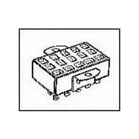
S-303-AB
Description
CONN SOCKET 3POS W/BRKT PNL MNT
Manufacturer
Cinch Connectors
Series
300r
Type
Cable Socketr
Specifications of S-303-AB
Connector Type
Receptacle, Jones
Contact Type
Female Socket
Number Of Positions
3
Pitch
0.156" (3.96mm)
Number Of Rows
1
Mounting Type
Panel Mount
Cable Termination
Solder Eyelet
Wire Type
Discrete
Contact Finish
Cadmium
Color
Black
Contact Termination
Solder
No. Of Contacts
3
No. Of Rows
1
Connector Mounting
Panel
Gender
Receptacle
Contact Material
Phosphor Bronze
Agency Approvals
CSA, UL
Angle
Straight
Brand/series
300 Series
Contact Plating
Cadmium
Current, Rating
10 A
Diameter
0.152 in. (Hole)
Flammability Rating
UL94V-0
Length, Overall
1 "
Material, Contact
Phosphor Bronze
Material, Dielectric
Phenolic
Material, Hood
Thermoplastic
Material, Insulation
Phenolic Molded Monoblock
Number Of Contacts
3
Plating, Contact
Cadmium
Primary Type
Jones
Special Features
Polarized
Standards
UL Recognized, CSA Certified
Temperature, Operating
0 to +105 °C
Termination
Solder
Thickness
0.438 in.
Voltage, Rating
250 V
Width
1.000 in.
Rohs Compliant
No
Housing Material
Thermoplastic
Number Of Positions / Contacts
3
Voltage Rating
250 V
Lead Free Status / RoHS Status
Contains lead / RoHS non-compliant
Features
-
Contact Finish Thickness
-
Row Spacing
-
Fastening Type
-
For Use With
For use in cable-to-cable and cable-to-panel applications
Lead Free Status / Rohs Status
No RoHS Version Available
Other names
CJ303S
S-303-AB-P
S303AB-P
S-303-AB-P
S303AB-P


CN0942 Series: Fluorosilicone Inserts
T
Designator
*
**
NOTES:
1
CN0944 Series: Neoprene Inserts
Termination Term
Designator Type
*
**
NOTES:
1
CN0942/CN0944 Series (C48 Family)
Short Receptacle Connectors
Non-Removable Contacts
ermination Contact Termination
For other modifications, class, etc., consult factory.
For mounting hole dimensions, see page 3-20.
For other modifications, class, etc., consult factory.
For mounting hole dimensions, see page 3-20.
01*
02*
03**
04**
06*
01*
02*
03**
04**
06*
Applies to CN0944B/CN0944C.
Applies to CN0944D/CN0944E.
Applies to CN0942B/CN0942C.
Applies to CN0942D/CN0942E.
T & W
P & S
X & Y
P & S
Style
X & Y
W
B
C
B
C
T Min. S + .002
T Min. S + .002
.250
.230
.144
.124
.900
.250
.230
.144
.124
.900
Termination
.025
.025
.025
.025
.025
.025
N/A
N/A
N/A
N/A
Ordering Information
Series Designation
Series Modification
B - Square-Flange Mount Bayonet Coupled
C - Square-Flange Mount Thread Coupled
D - Single-Hole Mount Bayonet Coupled
E - Single-Hole Mount Thread Coupled
Shell Size
8, 10, 12, 14, 16, 18, 20, 22, & 24
Class
G - Cadmium/Nickel Finish
J - Anodized Finish
N - Electroless Nickel Finish
Insert Arrangement
(See page 3-4)
Series Designation
CN0944
Series Modification
B - Square-Flange Mount Bayonet Coupled
C - Square-Flange Mount Thread Coupled
D - Single-Hole Mount Bayonet Coupled
E - Single-Hole Mount Thread Coupled
Shell Size
8, 10, 12, 14, 16, 18, 20, 22, & 24
Ordering Information
Environmental Class
G - Cadmium/Nickel Finish
N - Electroless Nickel Finish
R - Anodized Finish
3-10
1
CN0942 B 10 J 05 P N O1
1
CN0944 B 10 R 05 P N C O1
Call Toll Free: 1 (800) 323-9612
Contact Style
• Solder Pin Terminal
P - Pin
S - Socket
• Solder Cup Terminal
X - Pin
Y - Socket
• Wire Wrap Terminal
T - Pin
W - Socket
Termination
(See table)
Shell Position
N, 6, 7, 8, 9, Y (See page 3-4)
Termination
(See table)
Termination Type
B - Solder Pin
C - Solder Cup
W - Wire Wrap
Shell Position
N, 6, 7, 8, 9, Y (See page 3-4)
Contact Style
P - Pin
S - Socket
Insert Arrangement
(See page 3-4)
3
Related parts for S-303-AB
Image
Part Number
Description
Manufacturer
Datasheet
Request
R

Part Number:
Description:
CONN SOCKET 3POS JONES SOLDER
Manufacturer:
Cinch Connectors
Datasheet:

Part Number:
Description:
CONN SOCKET 3POS W/KEEPER JONES
Manufacturer:
Cinch Connectors
Datasheet:

Part Number:
Description:
Jones Plugs & Sockets 3C PNL MNT SOCKET
Manufacturer:
Cinch Connectors
Part Number:
Description:
CONN SOCKET 3POS W/BRKT PNL MNT
Manufacturer:
Cinch Connectors
Datasheet:
Part Number:
Description:
CONN SOCKET 3POS JONES SOLDER
Manufacturer:
Cinch Connectors
Datasheet: