16CTU04STRLPBF Vishay, 16CTU04STRLPBF Datasheet
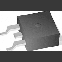
ULTRAFAST RECTIFIER, CMN CTHD 16A, D2PAK

16CTU04STRLPBF

Manufacturer Part Number
16CTU04STRLPBF
Description
ULTRAFAST RECTIFIER, CMN CTHD 16A, D2PAK
Manufacturer
Vishay
Datasheet

Specifications of 16CTU04STRLPBF

Repetitive Reverse Voltage Vrrm Max
400V
Forward Current If(av)
16A
Forward Voltage Vf Max
1.3V
Diode Configuration
Dual Common Cathode
Diode Type
Fast Recovery
Lead Free Status / RoHS Status
Lead free / RoHS Compliant

Available stocks

Company
Part Number
Manufacturer
Quantity
Price
Part Number:
16CTU04STRLPBF
Manufacturer:
VIR
Quantity:
800
Document Number: 94009
Revision: 11-Mar-10
PRODUCT SUMMARY
ABSOLUTE MAXIMUM RATINGS
PARAMETER
Peak repetitive reverse voltage
Average rectified forward current
Non-repetitive peak surge current
Peak repetitive forward current
Operating junction and storage temperatures
ELECTRICAL SPECIFICATIONS PER LEG (T
PARAMETER
Breakdown voltage,
blocking voltage
Forward voltage
Reverse leakage current
Junction capacitance
Series inductance
V -16CTU04 P F
Anode
1
Common
I
Cathode
Common
Cathode
D
F(AV)
V
t
Ba e
rr
2
R
PAK
2
2
Anode
3
SYMBOL
Ultrafast Rectifier, 2 x 8 A FRED Pt
V
C
V
V
L
I
BR
R
R
F
S
T
V -16CTU04-1P F
,
Anode
total device
1
For technical questions, contact:
Common
Cathode
Common
Cathode
TO-262
I
I
I
V
T
V
Measured lead to lead 5 mm from package body
Ba e
per leg
R
F
F
R
J
R
2 x 8 A
= 8 A
= 8 A, T
= 100 μA
400 V
60 ns
= 150 °C, V
= V
= 400 V
2
2
Anode
R
rated
3
J
SYMBOL
= 150 °C
T
V
I
J
I
I
TEST CONDITIONS
F(AV)
FSM
FRM
, T
RRM
R
= V
VS-16CTU04SPbF, VS-16CTU04-1PbF
Stg
J
R
= 25 °C unless otherwise specified)
rated
Rated V
T
Rated V
C
= 25 °C
FEATURES
• Ultrafast recovery time
• Low forward voltage drop
• Low leakage current
• 175 °C operating junction temperature
• Meets MSL level 1, per J-STD-020, LF maximum
• Halogen-free according to IEC 61249-2-21
• Compliant to RoHS directive 2002/95/EC
• AEC-Q101 qualified
DESCRIPTION/APPLICATIONS
Vishay HPP’s FRED Pt
ultrafast recovery rectifiers specifically designed with
optimized performance of forward voltage drop and ultrafast
recovery time.
The planar structure and the platinum doped life time
control,
ruggedness and reliability characteristics.
These devices are intended for use in the output rectification
stage of SMPS, UPS, dc-to-dc converters as well as
freewheeling diode in low voltage inverters and chopper
motor drives.
Their extremely optimized stored charge and low recovery
current minimize the switching losses and reduce over
dissipation in the switching element and snubbers.
diodestech@vishay.com
peak of 260 °C
definition
R
R
, T
, square wave, 20 kHz, T
TEST CONDITIONS
C
= 155 °C
guarantee
Vishay High Power Products
MIN.
400
-
-
-
-
-
-
the
®
C
series are the state of the art
= 155 °C
®
best
TYP.
1.19
0.94
0.2
8.0
20
14
-
overall
- 65 to 175
VALUES
400
100
16
16
MAX.
8
500
1.3
1.0
10
-
-
-
www.vishay.com
performance,
UNITS
UNITS
°C
nH
V
A
μA
pF
V
1

Related parts for 16CTU04STRLPBF

16CTU04STRLPBF Summary of contents

Page 1

... 150 ° rated 400 V R Measured lead to lead 5 mm from package body For technical questions, contact: diodestech@vishay.com Vishay High Power Products ® ® series are the state of the art guarantee the best overall performance, VALUES 400 8 16 100 = 155 °C 16 ...

Page 2

... VS-16CTU04SPbF, VS-16CTU04-1PbF Vishay High Power Products DYNAMIC RECOVERY CHARACTERISTICS PER LEG (T PARAMETER SYMBOL Reverse recovery time Peak recovery current Reverse recovery charge THERMAL - MECHANICAL SPECIFICATIONS PARAMETER SYMBOL Maximum junction and storage T temperature range Thermal resistance, junction to case per leg Thermal resistance, ...

Page 3

... V - Reverse Voltage (V) R Fig Typical Junction Capacitance vs. Reverse Voltage 0.01 0.001 0. Rectangular Pulse Duration (s) 1 thJC For technical questions, contact: diodestech@vishay.com Vishay High Power Products T = 175 ° 150 ° 125 ° 100 ° ° 100 200 ...

Page 4

... VS-16CTU04SPbF, VS-16CTU04-1PbF Vishay High Power Products 180 170 160 150 Square wave (D = 0.50) Rated V applied 140 R See note (1) 130 Average Forward Current (A) F(AV) Fig Maximum Allowable Case Temperature vs. Average Forward Current Average Forward Current (A) F(AV) Fig Forward Power Loss Characteristics Note ...

Page 5

... I RRM (5) dI /dt - peak rate of change of (rec)M current during t to point where a line pa ing and 0.50 I RRM RRM Fig Reverse Recovery Waveform and Definitions For technical questions, contact: diodestech@vishay.com Vishay High Power Products b (4) rr 0.5 I RRM (5) dI /dt (rec)M RRM ...

Page 6

... VS-16CTU04SPbF, VS-16CTU04-1PbF Vishay High Power Products ORDERING INFORMATION TABLE Device code VS Dimensions Part marking information Packaging information www.vishay.com 6 Ultrafast Rectifier, ® FRED HPP product suffix Current rating ( Common cathode TO-220, D PAK U = Ultrafast recovery Voltage rating (04 = 400 PAK -1 = TO-262 None = Tube (50 pieces) ...

Page 7

... Vishay product could result in personal injury or death. Customers using or selling Vishay products not expressly indicated for use in such applications their own risk and agree to fully indemnify and hold Vishay and its distributors harmless from and against any and all claims, liabilities, expenses and damages arising or resulting in connection with such use or sale, including attorneys fees, even if such claim alleges that Vishay or its distributor was negligent regarding the design or manufacture of the part ...

Related keywords