MBR160 Vishay, MBR160 Datasheet - Page 3
MBR160
Manufacturer Part Number
MBR160
Description
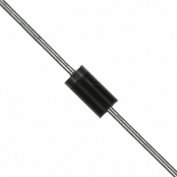
SCHOTTKY RECTIFIER, 1A 60V DO-204AL
Manufacturer
Vishay
Specifications of MBR160
Repetitive Reverse Voltage Vrrm Max
60V
Forward Current If(av)
1A
Forward Voltage Vf Max
1V
Forward Surge Current Ifsm Max
150A
Operating Temperature Range
-40°C To +150°C
Diode Type
Schottky
Voltage - Forward (vf) (max) @ If
750mV @ 1A
Voltage - Dc Reverse (vr) (max)
60V
Current - Average Rectified (io)
1A
Current - Reverse Leakage @ Vr
500µA @ 60V
Speed
Fast Recovery =< 500ns, > 200mA (Io)
Mounting Type
Through Hole
Package / Case
DO-204AL, DO-41, Axial
Product
Schottky Diodes
Peak Reverse Voltage
60 V
Forward Continuous Current
1 A
Max Surge Current
150 A
Configuration
Single
Forward Voltage Drop
0.75 V
Maximum Reverse Leakage Current
500 uA
Mounting Style
Through Hole
Lead Free Status / RoHS Status
Lead free / RoHS Compliant
Reverse Recovery Time (trr)
-
Capacitance @ Vr, F
-
Lead Free Status / Rohs Status
Lead free / RoHS Compliant
Other names
*MBR160
Available stocks
Company
Part Number
Manufacturer
Quantity
Price

Part Number:
MBR160
Manufacturer:
VISHAY/威世
Quantity:
20 000
Part Number:
MBR160FT1G
Manufacturer:
ZXLL
Quantity:
20 000
Company:
Part Number:
MBR160RGL
Manufacturer:
ON
Quantity:
125 000
Part Number:
MBR160RGL
Manufacturer:
VISHAY/威世
Quantity:
20 000
Company:
Part Number:
MBR160RLG
Manufacturer:
ON
Quantity:
15 300
Part Number:
MBR160RLG
Manufacturer:
0N
Quantity:
20 000


Note
(1)
Document Number: 93439
Revision: 06-Nov-08
Formula used: T
Pd = Forward power loss = I
Fig. 1 - Maximum Forward Voltage Drop Characteristics
0.1
10
0.0001
1
0.001
0
0.01
100
0.1
Fig. 2 - Typical Values of Reverse Current vs.
10
1
0.2
0
C
= T
Forward Voltage Drop - V
10
J
0.4
- (Pd + Pd
Reverse Voltage - V
20
Reverse Voltage
0.6
F(AV)
30
T = 150˚C
0.8
REV
x V
J
40
FM
) x R
125˚C
25˚C
For technical questions, contact: diodes-tech@vishay.com
at (I
Tj = 150˚C
Tj = 125˚C
Tj = 25˚C
1
thJC
50
R
(V)
F(AV)
FM
1.2
;
(V)
60
/D) (see fig. 6); Pd
1.4
Schottky Rectifier, 1 A
70
1.6
REV
= Inverse power loss = V
Average Forward Current, Printed Circuit Board Mounted
Fig. 3 - Typical Junction Capacitance vs. Reverse Voltage
160
140
120
100
Fig. 4 - Maximum Ambient Temperature vs.
100
0.8
0.6
0.4
0.2
80
60
40
20
Fig. 5 - Forward Power Loss Characteristics
10
Vishay High Power Products
0
1
0
0
0
0
Average Forward Current - I
Average Forward Current - I
Square wave (D = 0.50)
80% Rated Vr applied
see note (1)
0.2 0.4 0.6 0.8
RMS Limit
0.2 0.4 0.6 0.8
R1
10
x I
Reverse Voltage - V
R
MBR150, MBR160
20
(1 - D); I
T = 25˚C
30
J
DC
R
40
at V
1
1
R1
50
1.2 1.4 1.6
R
1.2 1.4 1.6
(V)
D = 0.20
D = 0.25
D = 0.33
D = 0.50
D = 0.75
DC
= 80 % rated V
F(AV)
F(AV)
60
www.vishay.com
(A)
(A)
70
R
3
Related parts for MBR160
Image
Part Number
Description
Manufacturer
Datasheet
Request
R

Part Number:
Description:
357-036-542-201 CARDEDGE 36POS DL .156 BLK LOPRO
Manufacturer:
Vishay
Datasheet:
Part Number:
Description:
357-036-542-201 CARDEDGE 36POS DL .156 BLK LOPRO
Manufacturer:
Vishay
Datasheet:
Part Number:
Description:
357-036-542-201 CARDEDGE 36POS DL .156 BLK LOPRO
Manufacturer:
Vishay
Datasheet:
Part Number:
Description:
357-036-542-201 CARDEDGE 36POS DL .156 BLK LOPRO
Manufacturer:
Vishay
Datasheet:
Part Number:
Description:
357-036-542-201 CARDEDGE 36POS DL .156 BLK LOPRO
Manufacturer:
Vishay
Datasheet:
Part Number:
Description:
357-036-542-201 CARDEDGE 36POS DL .156 BLK LOPRO
Manufacturer:
Vishay
Datasheet:
Part Number:
Description:
357-036-542-201 CARDEDGE 36POS DL .156 BLK LOPRO
Manufacturer:
Vishay
Datasheet:
Part Number:
Description:
357-036-542-201 CARDEDGE 36POS DL .156 BLK LOPRO
Manufacturer:
Vishay
Datasheet:
Part Number:
Description:
357-036-542-201 CARDEDGE 36POS DL .156 BLK LOPRO
Manufacturer:
Vishay
Datasheet:
Part Number:
Description:
357-036-542-201 CARDEDGE 36POS DL .156 BLK LOPRO
Manufacturer:
Vishay
Datasheet:
Part Number:
Description:
357-036-542-201 CARDEDGE 36POS DL .156 BLK LOPRO
Manufacturer:
Vishay
Datasheet:
Part Number:
Description:
357-036-542-201 CARDEDGE 36POS DL .156 BLK LOPRO
Manufacturer:
Vishay
Datasheet:
Part Number:
Description:
357-036-542-201 CARDEDGE 36POS DL .156 BLK LOPRO
Manufacturer:
Vishay
Datasheet:
Part Number:
Description:
357-036-542-201 CARDEDGE 36POS DL .156 BLK LOPRO
Manufacturer:
Vishay
Datasheet:
Part Number:
Description:
357-036-542-201 CARDEDGE 36POS DL .156 BLK LOPRO
Manufacturer:
Vishay
Datasheet: