VS-50WQ03FNPBF Vishay, VS-50WQ03FNPBF Datasheet - Page 2
VS-50WQ03FNPBF
Manufacturer Part Number
VS-50WQ03FNPBF
Description
SCHOTTKY RECTIFIER, 5.5A, 30V, DPAK
Manufacturer
Vishay
Specifications of VS-50WQ03FNPBF
Repetitive Reverse Voltage Vrrm Max
30V
Forward Current If(av)
5.5A
Forward Voltage Vf Max
350mV
Forward Surge Current Ifsm Max
320A
Diode Type
Schottky
Product
Schottky Rectifiers
Peak Reverse Voltage
30 V
Forward Continuous Current
5.5 A
Max Surge Current
320 A
Configuration
Single Dual Anode
Forward Voltage Drop
0.53 V at 10 A
Maximum Reverse Leakage Current
3000 uA
Operating Temperature Range
- 40 C to + 150 C
Mounting Style
SMD/SMT
Package / Case
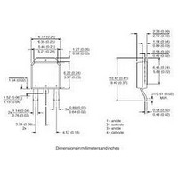
DPAK (TO-252AA)
Lead Free Status / RoHS Status
Lead free / RoHS Compliant


Document Number: 94232
Bulletin PD-21091 rev. B 08/06
Electrical Specifications
50WQ03FNPbF
Absolute Maximum Ratings
Voltage Ratings
Thermal-Mechanical Specifications
V
V
I
I
E
I
V
I
V
r
C
L
(1) Pulse Width < 300μs, Duty Cycle < 2%
T
T
R
wt
(*) dPtot
RM
F(AV)
FSM
AR
t
S
R
RWM
AS
FM
F(TO)
J
stg
T
thJC
dTj
Part number
Max. DC Reverse Voltage (V)
Max. Working Peak Reverse Voltage (V)
Parameters
Max. Average Forward Current
* See Fig. 5
Max. Peak One Cycle Non-Repetitive
Surge Current * See Fig. 7
Non-Repetitive Avalanche Energy
Repetitive Avalanche Current
Max. Forward Voltage Drop
* See Fig. 1
Max. Reverse Leakage Current
* See Fig. 2
Threshold Voltage
Forward Slope Resistance
Typical Junction Capacitance
Typical Series Inductance
Parameters
Max. Junction Temperature Range (*)
Max. Storage Temperature Range
Max. Thermal Resistance Junction
to Case
Approximate Weight
Case Style
Marking Device
Parameters
<
Rth( j-a)
1
thermal runaway condition for a diode on its own heatsink
(1)
(1)
50WQ...
50WQ...
-40 to 150
-40 to 150
0.3 (0.01)
22.22
50W...
320
130
0.46
0.53
0.35
0.46
0.19
5.5
2.0
50WQ03FN
590
10
5.0
58
3.0
3
D - PAK
Units
Units
Units
g (oz.)
°C/W DC operation
mJ
mA
mA
mΩ
nH
pF
°C
°C
A
A
A
V
V
V
V
V
Similar to TO-252AA
@
@ 10A
@
@ 10A
T
T
T
V
Measured lead to lead 5mm from package body
50% duty cycle @ T
5μs Sine or 3μs Rect. pulse
T
Current decaying linearly to zero in 1 μsec
Frequency limited by T
10ms Sine or 6ms Rect. pulse
J
J
J
R
J
= T
= 25 °C, I
= 25 °C
= 125 °C
= 5V
5A
5A
J
max.
DC
(test signal range 100Khz to 1Mhz) 25 °C
AS
50WQ03FNPbF
Conditions
Conditions
Conditions
= 2.0 Amps, L = 5 mH
* See Fig. 4
T
T
V
J
J
R
C
= 25 °C
= 125 °C
= 136°C, rectangular wave form
= rated V
30
J
max. V
R
A
= 1.5 x V
Following any rated
load condition and with
rated V
www.vishay.com
RRM
R
typical
applied
2
Related parts for VS-50WQ03FNPBF
Image
Part Number
Description
Manufacturer
Datasheet
Request
R

Part Number:
Description:
357-036-542-201 CARDEDGE 36POS DL .156 BLK LOPRO
Manufacturer:
Vishay
Datasheet:
Part Number:
Description:
357-036-542-201 CARDEDGE 36POS DL .156 BLK LOPRO
Manufacturer:
Vishay
Datasheet:
Part Number:
Description:
357-036-542-201 CARDEDGE 36POS DL .156 BLK LOPRO
Manufacturer:
Vishay
Datasheet:
Part Number:
Description:
357-036-542-201 CARDEDGE 36POS DL .156 BLK LOPRO
Manufacturer:
Vishay
Datasheet:
Part Number:
Description:
357-036-542-201 CARDEDGE 36POS DL .156 BLK LOPRO
Manufacturer:
Vishay
Datasheet:
Part Number:
Description:
357-036-542-201 CARDEDGE 36POS DL .156 BLK LOPRO
Manufacturer:
Vishay
Datasheet:
Part Number:
Description:
357-036-542-201 CARDEDGE 36POS DL .156 BLK LOPRO
Manufacturer:
Vishay
Datasheet:
Part Number:
Description:
357-036-542-201 CARDEDGE 36POS DL .156 BLK LOPRO
Manufacturer:
Vishay
Datasheet:
Part Number:
Description:
357-036-542-201 CARDEDGE 36POS DL .156 BLK LOPRO
Manufacturer:
Vishay
Datasheet:
Part Number:
Description:
357-036-542-201 CARDEDGE 36POS DL .156 BLK LOPRO
Manufacturer:
Vishay
Datasheet:
Part Number:
Description:
357-036-542-201 CARDEDGE 36POS DL .156 BLK LOPRO
Manufacturer:
Vishay
Datasheet:
Part Number:
Description:
357-036-542-201 CARDEDGE 36POS DL .156 BLK LOPRO
Manufacturer:
Vishay
Datasheet:
Part Number:
Description:
357-036-542-201 CARDEDGE 36POS DL .156 BLK LOPRO
Manufacturer:
Vishay
Datasheet:
Part Number:
Description:
357-036-542-201 CARDEDGE 36POS DL .156 BLK LOPRO
Manufacturer:
Vishay
Datasheet:
Part Number:
Description:
357-036-542-201 CARDEDGE 36POS DL .156 BLK LOPRO
Manufacturer:
Vishay
Datasheet: