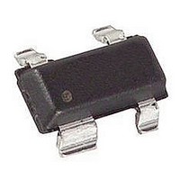
HSMS-2865-BLKG Avago Technologies US Inc., HSMS-2865-BLKG Datasheet - Page 11

HSMS-2865-BLKG
Manufacturer Part Number
HSMS-2865-BLKG
Description
RF DIODE, SCHOTTKY 0.3PF 7V SOT-143
Manufacturer
Avago Technologies US Inc.
Type
Schottky Dioder
Datasheet
1.HSMS-2860-BLKG.pdf
(18 pages)
Specifications of HSMS-2865-BLKG
Capacitance Ct
0.3pF
Diode Case Style
SOT-143
Series Resistance @ If
6ohm
Peak Reflow Compatible (260 C)
Yes
Leaded Process Compatible
Yes
Forward Voltage
350mV
Diode Type
RF Schottky
Package
4SOT-143
Configuration
Dual Parallel
Frequency Range
UHF|SHF
Maximum Forward Voltage
0.35@1mA V
Maximum Reverse Voltage
4 V
Maximum Processing Temperature
260 °C
Maximum Diode Capacitance
0.3(Typ) pF
Typical Video Resistance
5 KOhm
Typical Voltage Sensitivity
25@5.8GHz mV/uW
Typical Tangential Sensitivity
-55@5.8GHz dB
Pin Count
3 +Tab
Package Type
SOT-143
Breakdown Voltage
7V
Package / Case
SOT-143
Rohs Compliant
Yes
Forward Current If Max
1mA
Forward Voltage Vf Max
350mV
No. Of Pins
4
Lead Free Status / RoHS Status
Lead free / RoHS Compliant
Available stocks
Company
Part Number
Manufacturer
Quantity
Price
Company:
Part Number:
HSMS-2865-BLKG
Manufacturer:
AVAGO
Quantity:
10
Figure 25. Output Voltage vs. Temperature and Bias Current
in the 915 MHz Voltage Doubler using the HSMS-286C.
Figure 26. Output Voltage vs. Temperature and Bias Current
in the 5.80 GHz Voltage Detector using the HSMS-286B Schottky.
Six Lead Circuits
The differential detector is often used to provide temper‑
ature compensation for a Schottky detector, as shown in
Figures 27 and 28.
Figure 27. Differential Detector.
Figure 28. Conventional Differential Detector.
These circuits depend upon the use of two diodes
having matched V
temperatures. This is best achieved by using two diodes
11
matching
PA
network
120
100
80
60
40
35
25
15
5
-55
-55
-35
-35
1.0 µA
10 µA
3.0 µA
0.5 µA
bias
3.0 µA
1.0 µA
10 µA
0.5 µA
-15
-15
HSMS-2865
TEMPERATURE (
TEMPERATURE (
f
INPUT POWER = – 30 dBm
INPUT POWER = –30 dBm
characteristics over all operating
5
5
detector
diode
25
25
reference diode
differential
amplifier
°
45
C)
°
V
C)
45
s
65
65
to differential
amplifier
85
85
in a single package, such as the SOT‑143 HSMS‑2865 as
shown in Figure 29.
In high power differential detectors, RF coupling from
the detector diode to the reference diode produces a
rectified voltage in the latter, resulting in errors.
Isolation between the two diodes can be obtained
by using the HSMS‑286K diode with leads 2 and 5
grounded. The difference between this product and the
conventional HSMS‑2865 can be seen in Figure 29.
Figure 29. Comparing Two Diodes.
The HSMS‑286K, with leads 2 and 5 grounded, offers
some isolation from RF coupling between the diodes.
This product is used in a differential detector as shown
in Figure 30.
Figure 30. High Isolation Differential Detector.
In order to achieve the maximum isolation, the designer
must take care to minimize the distance from leads 2
and 5 and their respective ground via holes.
Tests were run on the HSMS‑282K and the conventional
HSMS‑2825 pair, which compare with each other in the
same way as the HSMS‑2865 and HSMS‑286K, with the
results shown in Figure 31.
Figure 31. Comparing HSMS-282K with HSMS-2825.
PA
5000
1000
3
100
0.5
10
1
1
-35
HSMS-2865
Frequency = 900 MHz
SOT-143
Square law
response
-25
INPUT POWER (dBm)
HSMS-286K
4
2
-15
37 dB
47 dB
detector
diode
-5
reference diode
HSMS-2825
ref. diode
RF diode
V
6
1
out
HSMS-286K
V
SOT-363
s
5
2
5
HSMS-282K
ref. diode
to differential
4
15
3
amplifier


