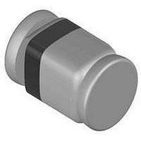
BZM55C3V9-TR Vishay, BZM55C3V9-TR Datasheet

BZM55C3V9-TR
Specifications of BZM55C3V9-TR
Available stocks
Related parts for BZM55C3V9-TR
BZM55C3V9-TR Summary of contents
Page 1
... Packaging codes/options 2.5k per 7" reel, 12.5k/box TR3 / 10k per 13" reel, 10k/box Test condition ≤ 300 K/W R thJA Test condition Symbol R thJA 2 R thJL Test condition Symbol V F BZM55..Series Vishay Semiconductors 9612315 Symbol Value P 500 175 175 stg Value ...
Page 2
... Zener Voltage 1) Range min max BZM55C2V4 2.28 2.56 BZM55C2V7 2.5 2.9 BZM55C3V0 2.8 3.2 BZM55C3V3 3.1 3.5 BZM55C3V6 3.4 3.8 BZM55C3V9 3.7 4.1 BZM55C4V3 4 4.6 BZM55C4V7 4.4 5 BZM55C5V1 4.8 5.4 BZM55C5V6 5.2 6 BZM55C6V2 5.8 6.6 BZM55C6V8 6.4 7.2 BZM55C7V5 7 7.9 BZM55C8V2 7 ...
Page 3
... T 25 °C zmin j BZM55..Series Vishay Semiconductors Test Reverse Leakage Current Current amb amb 25°C 150°C µA mA max -0.06 1 < 50 < ...
Page 4
... BZM55..Series Vishay Semiconductors Typical Characteristics (T 600 500 400 300 200 100 120 160 T – Ambient T emperature(° 9602 amb Figure 1. Total Power Dissipation vs. Ambient Temperature 1000 T =25°C j 100 I =5mA – Z-Voltage ( 9598 Z Figure 2. Typical Change of Working Voltage under Operating Conditions at T =25° ...
Page 5
... Rev. 7, 10-Jun-03 0.152 Figure 10. Board for R Reflow Soldering 1.2 35 Figure 11. Recommended foot pads (in mm) Wave Soldering 1.4 25 Figure 12. Recommended foot pads (in mm) BZM55..Series Vishay Semiconductors 0.71 1.3 1.27 9.9 0.355 definition (in mm) thJA 0.8 0.8 0.8 2.4 0.9 1.0 0.9 2 ...
Page 6
... BZM55..Series Vishay Semiconductors 1000 t /T=0.5 p 100 t /T=0 /T=0. /T=0.1 t /T=0. /T=0. – 9603 Package Dimensions in mm www.vishay.com 6 Single Pulse R =300K/W thJA T=T jmax 2 1 =(–V +(V +4r T thp – Pulse Length ( Figure 13. Thermal Response 96 12072 VISHAY –T amb )/( Document Number 85597 ...
Page 7
... Various national and international initiatives are pressing for an earlier ban on these substances. Vishay Semiconductor GmbH has been able to use its policy of continuous improvements to eliminate the use of ODSs listed in the following documents. 1. Annex A, B and list of transitional substances of the Montreal Protocol and the London Amendments respectively 2 ...
Page 8
This datasheet has been download from: www.datasheetcatalog.com Datasheets for electronics components. ...


