PS21867 Powerex Inc, PS21867 Datasheet - Page 4
PS21867
Manufacturer Part Number
PS21867
Description
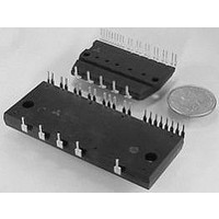
IGBT MODULE, 600V, 30A, DIP
Manufacturer
Powerex Inc
Datasheet
1.PS21867.pdf
(6 pages)
Specifications of PS21867
Transistor Polarity
N And P Channel
Dc Collector Current
30A
Collector Emitter Voltage Vces
600V
Power Dissipation Pd
60.6W
Collector Emitter Voltage V(br)ceo
600V
Available stocks
Company
Part Number
Manufacturer
Quantity
Price
Company:

Part Number:
PS21867
Manufacturer:
MITSUBISHI
Quantity:
55
Company:
Part Number:
PS21867-A
Manufacturer:
MITSUBISHI
Quantity:
56
Company:
Part Number:
PS21867-A
Manufacturer:
MITSUBISHI
Quantity:
300
Part Number:
PS21867-A
Manufacturer:
MITSUIBI
Quantity:
20 000
Company:
Part Number:
PS21867-AP
Manufacturer:
MITSUBISHI
Quantity:
56
Company:
Part Number:
PS21867-AP
Manufacturer:
MITSUBISHI
Quantity:
300
Part Number:
PS21867-P
Manufacturer:
MITSUBISHI/三菱
Quantity:
20 000


4
Powerex, Inc., 200 E. Hillis Street, Youngwood, Pennsylvania 15697-1800 (724) 925-7272
PS21867-P
Intellimod™ Module
Dual-In-Line Intelligent Power Module
30 Amperes/600 Volts
Electrical and Mechanical Characteristics, T
Characteristics
Supply Voltage
Circuit Current
Fault Output Voltage
Input Current
Short-Circuit Trip Level*
Supply Circuit Undervoltage
Protection
Fault Output Pulse Width**
ON Threshold Voltage
OFF Threshold Voltage
Thermal Characteristics
Characteristic
Junction to Fin
Thermal Resistance
* Short-Circuit protection is functioning only at the lower arms. Please select the value of the external shunt resistor such that the SC trip level is less than 51A.
**Fault signal is asserted when the lower arm short circuit or control supply under-voltage protective functions operate. The fault output pulse-width t
Control Sector
of C
FO
according to the following approximate equation: C
V
R
R
UV
UV
V
V
Symbol
Symbol
V
V
UV
UV
SC(ref)
th(j-f)Q
th(j-f)D
V
th(on)
th(off)
t
V
FOH
FOL
I
I
FO
IN
DB
D
DBr
FO
DBt
D
Dr
Dt
= (12.2 x 10
V
V
V
-6
SC
Applied between V
j
UFB
UFB
) x t
Applied between U
= 25°C unless otherwise specified
= 0V, F
Applied between V
FO
FWDi Part (Per 1/6 Module)
Total of V
Total of V
-V
-V
IGBT Part (Per 1/6 Module)
V
V
V
V
V
{F} .
D
D
D
D
Reset Level, T
Reset Level, T
UFS
UFS
VFB
V
Trip Level, T
Trip Level, T
T
= V
= V
= V
= V
SC
j
U
O
= 25°C, V
, V
, V
-V
N
DB
DB
DB
DB
Circuit: 10kΩ to 5V Pull-up
C
= 1V, I
, V
VFS
VFB
VFB
P1
P1
V
FO
= 15V, V
= 15V, V
= 15V, V
= 15V, V
IN
N
Test Conditions
-V
-V
, W
, V
= 22nF
-V
-V
= 5V
Condition
P1
PC
PC
FO
VFS
VFS
j
j
WFB
D
N
P
≤ 125°C
≤ 125°C
j
j
-V
, V
, V
, V
-V
≤ 125°C
≤ 125°C
UFB
= 1mA
= 15V
PC
, V
, V
IN
IN
IN
IN
P
NC
N1
N1
-V
, W
, V
-V
WFB
WFB
WFS
= 5V,
= 0V,
= 5V,
= 0V,
-V
-V
P
UFS
N1
NC
NC
-V
-V
-V
-V
PC,
,
WFS
WFS
NC
13.5
13.0
0.43
10.0
10.5
10.3
10.8
Min.
Min.
4.9
1.0
1.0
2.1
0.8
—
—
—
—
—
—
—
FO
15.0
15.0
1.50
0.48
depends on the capacitance value
Typ.
1.8
2.3
1.4
Typ.
—
—
—
—
—
—
—
—
—
—
—
—
Max.
16.5
18.5
5.00
7.00
0.40
0.55
0.95
2.00
0.53
12.0
12.5
12.5
13.0
Max.
1.65
3.00
2.6
2.1
—
—
°C/Watt
°C/Watt
Volts
Volts
Volts
Volts
Volts
Volts
Volts
Volts
Volts
Volts
Volts
Units
Units
mA
mA
mA
mA
mA
ms
Related parts for PS21867
Image
Part Number
Description
Manufacturer
Datasheet
Request
R

Part Number:
Description:
Manufacturer:
Powerex Inc
Datasheet:
Part Number:
Description:
Manufacturer:
Powerex Inc
Datasheet:
Part Number:
Description:
Manufacturer:
Powerex Inc
Datasheet:
Part Number:
Description:
Manufacturer:
Powerex Inc
Datasheet:
Part Number:
Description:
Manufacturer:
Powerex Inc
Datasheet:
Part Number:
Description:
Manufacturer:
Powerex Inc
Datasheet:
Part Number:
Description:
Manufacturer:
Powerex Inc
Datasheet:
Part Number:
Description:
Manufacturer:
Powerex Inc
Datasheet:
Part Number:
Description:
Manufacturer:
Powerex Inc
Datasheet:
Part Number:
Description:
Manufacturer:
Powerex Inc
Datasheet:
Part Number:
Description:
Manufacturer:
Powerex Inc
Datasheet:
Part Number:
Description:
Manufacturer:
Powerex Inc
Datasheet:
Part Number:
Description:
Manufacturer:
Powerex Inc
Datasheet:
Part Number:
Description:
Manufacturer:
Powerex Inc
Datasheet: