VSKT250-16 Vishay, VSKT250-16 Datasheet - Page 5
VSKT250-16
Manufacturer Part Number
VSKT250-16
Description
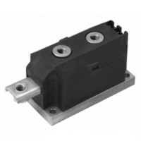
SCR THYRISTOR, 250A 1.6KV ADD-A-PAK
Manufacturer
Vishay
Specifications of VSKT250-16
Peak Repetitive Off-state Voltage, Vdrm
1.6kV
Current It Av
250A
Peak Non Rep Surge Current Itsm 50hz
8.9kA
Operating Temperature Range
-40°C To +125°C
Thyristor Case
ADD-A-Pak
No. Of Pins
7
Structure
Series Connection - All SCRs
Number Of Scrs, Diodes
2 SCRs
Voltage - Off State
1600V
Current - Gate Trigger (igt) (max)
200mA
Current - On State (it (av)) (max)
250A
Current - On State (it (rms)) (max)
555A
Current - Non Rep. Surge 50, 60hz (itsm)
8500A, 8900A
Current - Hold (ih) (max)
500mA
Mounting Type
Chassis Mount
Package / Case
3-MAGN-A-PAK™
Rated Repetitive Off-state Voltage Vdrm
1600 V
Off-state Leakage Current @ Vdrm Idrm
50 mA
Holding Current (ih Max)
500 mA
Maximum Operating Temperature
+ 130 C
Minimum Operating Temperature
- 40 C
Mounting Style
Screw
Breakover Current Ibo Max
8900 A
Gate Trigger Current (igt)
200 mA
Gate Trigger Voltage (vgt)
3 V
Maximum Gate Peak Inverse Voltage
5 V
Repetitive Peak Forward Blocking Voltage
1600 V
Lead Free Status / RoHS Status
Lead free / RoHS Compliant
Lead Free Status / RoHS Status
Lead free / RoHS Compliant, Contains lead / RoHS non-compliant
Other names
*IRKT250-16
IRKT250-16
IRKT250-16
IRKT250-16
IRKT250-16


Document Number: 93581
Revision: 02-Jul-10
Fig. 8 - Maximum Non-Repetitive Surge Current
6500
6000
5500
5000
4500
4000
3500
3000
2500
2000
1500
Numb er Of Equal Amplitude Half Cyc le Current Pulses (N)
1
VSK.250.. S eries
Per Junc tion
At Any Ra ted Loa d Cond ition And With
Rated V
R RM
DiodesAmericas@vishay.com, DiodesAsia@vishay.com,
1800
1600
1400
1200
1000
1200
1000
800
600
400
200
800
600
400
200
Ap p lied Following Surge.
For technical questions within your region, please contact one of the following:
Standard Recovery Diodes, 250 A to 320 A
0
0
10
0
0
Initia l T = 150°C
@ 60 Hz 0.0083 s
@ 50 Hz 0.0100 s
100 200 300 400 500 600 700 800
100
(MAGN-A-PAK Power Modules)
T otal Output Current (A)
T otal Outp ut Current (A)
J
200
(Rec t)
Fig. 6 - Forward Power Loss Characteristics
Fig. 7 - Forward Power Loss Characteristics
120°
100
3 x VSK.250.. S eries
T hree Phase Brid ge
S ingle Phase B rid ge
2 x VSK.250.. S eries
Connec ted
300
Connec ted
T = 150°C
(R ec t)
T = 150°C
(S ine)
180°
180°
J
J
400
VSK.250, VSK.270, VSK.320 Series
500
0
0
Maximum Allowab le Ambient T emp era ture (°C)
Maximum Allowable Ambient T emperature (°C)
25
25
50
50
Fig. 9 - Maximum Non-Repetitive Surge Current
DiodesEurope@vishay.com
7000
6500
6000
5500
5000
4500
4000
3500
3000
2500
2000
1500
75
75
0.01
Maximum Non Repetitive S urge Current
VSK.250.. S eries
Per Junc tion
100
100
Pulse T rain Duration (s)
125
125
Vishay Semiconductors
Versus Pulse T rain Duration.
R a ted V
No Voltage Reapp lied
150
150
0.1
Initial T = 150°C
R R M
Rea pplied
J
www.vishay.com
1
5
Related parts for VSKT250-16
Image
Part Number
Description
Manufacturer
Datasheet
Request
R

Part Number:
Description:
SCR DBL HISCR 400V 230A MAGNAPAK
Manufacturer:
Vishay
Datasheet:
Part Number:
Description:
SCR DBL HISCR 800V 230A MAGNAPAK
Manufacturer:
Vishay
Datasheet:
Part Number:
Description:
SCR DBL HISCR 1200V 230A MAGNPAK
Manufacturer:
Vishay
Datasheet:
Part Number:
Description:
SCR DBL HISCR 1400V 230A MAGNPAK
Manufacturer:
Vishay
Datasheet:

Part Number:
Description:
SCR Modules 250 Amp 1600 Volt 550 Amp IT(RMS)
Manufacturer:
Vishay
Datasheet:

Part Number:
Description:
STANDARD RECOVERY DIODES, 250 TO 320 A (MAGN-A-PAK POWER MODULES)
Manufacturer:
Vishay
Part Number:
Description:
SCR Modules 250 Amp 1400 Volt 550 Amp IT(RMS)
Manufacturer:
Vishay
Part Number:
Description:
SCR Modules 250 Amp 800 Volt 550 Amp IT(RMS)
Manufacturer:
Vishay
Datasheet:
Part Number:
Description:
SCR Modules 250 Amp 400 Volt 550 Amp IT(RMS)
Manufacturer:
Vishay
Part Number:
Description:
357-036-542-201 CARDEDGE 36POS DL .156 BLK LOPRO
Manufacturer:
Vishay
Datasheet:
Part Number:
Description:
357-036-542-201 CARDEDGE 36POS DL .156 BLK LOPRO
Manufacturer:
Vishay
Datasheet:
Part Number:
Description:
357-036-542-201 CARDEDGE 36POS DL .156 BLK LOPRO
Manufacturer:
Vishay
Datasheet:
Part Number:
Description:
357-036-542-201 CARDEDGE 36POS DL .156 BLK LOPRO
Manufacturer:
Vishay
Datasheet:
Part Number:
Description:
357-036-542-201 CARDEDGE 36POS DL .156 BLK LOPRO
Manufacturer:
Vishay
Datasheet: