VS-81RIA120PBF Vishay, VS-81RIA120PBF Datasheet - Page 2
VS-81RIA120PBF
Manufacturer Part Number
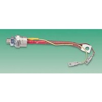
VS-81RIA120PBF
Description
THYRISTOR, 80A, 1200V, TO-94
Manufacturer
Vishay
Datasheet
1.VS-81RIA80PBF.pdf
(8 pages)
Specifications of VS-81RIA120PBF
Peak Repetitive Off-state Voltage, Vdrm
1200V
Gate Trigger Current Max, Igt
120mA
Current It Av
80A
On State Rms Current It(rms)
125A
Holding Current Max Ih
200mA
Gate Trigger Voltage Max Vgt
2.5V
Lead Free Status / RoHS Status
Lead free / RoHS Compliant


Bulletin 20040 rev. A 09/01
Absolute Maximum Ratings
2
81CNQ...A Series
Voltage Ratings
Electrical Specifications
Thermal-Mechanical Specifications
I
I
E
I
V
I
C
L
dv/dt Max. Voltage Rate of Change
T
T
R
R
R
wt
T
V
V
F(AV)
FSM
AR
RM
S
J
stg
AS
FM
T
thJC
thJC
thCS
R
RWM
Parameters
Max. Average Forward Current
* See Fig. 5
Max. Peak One Cycle Non-Repetitive
Surge Current (Per Leg) * See Fig. 7
Non-Repetitive Avalanche Energy
(Per Leg)
Repetitive Avalanche Current
(Per Leg)
Parameters
Max. Forward Voltage Drop
(Per Leg) * See Fig. 1
Max. Reverse Leakage Current
(Per Leg) * See Fig. 2
Max. Junction Capacitance (Per Leg)
Typical Series Inductance (Per Leg)
(Rated V
Parameters
Max. Junction Temperature Range
Max. Storage Temperature Range
Max. Thermal Resistance Junction
to Case (Per Leg)
Max. Thermal Resistance Junction
to Case (Per Package)
Typical Thermal Resistance, Case
to Heatsink (D61-8 Only)
Approximate Weight
Mounting Torque
(D61-8 Only)
Part number
Max. DC Reverse Voltage (V)
Max. Working Peak Reverse Voltage (V)
R
)
(1)
(1)
Min.
Max.
81CNQ Units
81CNQ Units
81CNQ Units
7.8 (0.28)
-55 to 175
-55 to 175
40 (35)
58 (50)
10000
4600
2600
0.60
0.74
0.54
0.66
0.85
0.42
0.30
790
5.5
80
54
45
8
5
g (oz.)
Kg-cm
(Ibf-in)
V/ µs
°C/W DC operation
°C/W DC operation
°C/W Mounting surface , smooth and greased
mA
mA
mJ
81CNQ035A
pF
nH
°C
°C
A
A
A
V
V
V
V
50% duty cycle @ T
5µs Sine or 3µs Rect. pulse
10ms Sine or 6ms Rect. pulse
T
Current decaying linearly to zero in 1 µsec
Frequency limited by T
@ 40A
@ 80A
@ 40A
@ 80A
T
T
V
Device flatness < 5 mils
Measured lead to lead 5mm from package body
35
J
J
J
R
= 25 °C, I
= 25 °C
= 125 °C
= 5V
DC
, (test signal range 100Khz to 1Mhz) 25°C
Conditions
Conditions
Conditions
AS
= 8 Amps, L = 1.7 mH
81CNQ040A
(1) Pulse Width < 300µs, Duty Cycle <2%
V
T
T
J
J
R
* See Fig. 4
= 125 °C
C
= 25 °C
= rated V
= 141 °C, rectangular wave form
40
J
max. V
R
Following any rated
load condition and with
rated V
A
= 1.5 x V
81CNQ045A
RRM
www.irf.com
R
applied
typical
45
Related parts for VS-81RIA120PBF
Image
Part Number
Description
Manufacturer
Datasheet
Request
R

Part Number:
Description:
357-036-542-201 CARDEDGE 36POS DL .156 BLK LOPRO
Manufacturer:
Vishay
Datasheet:
Part Number:
Description:
357-036-542-201 CARDEDGE 36POS DL .156 BLK LOPRO
Manufacturer:
Vishay
Datasheet:
Part Number:
Description:
357-036-542-201 CARDEDGE 36POS DL .156 BLK LOPRO
Manufacturer:
Vishay
Datasheet:
Part Number:
Description:
357-036-542-201 CARDEDGE 36POS DL .156 BLK LOPRO
Manufacturer:
Vishay
Datasheet:
Part Number:
Description:
357-036-542-201 CARDEDGE 36POS DL .156 BLK LOPRO
Manufacturer:
Vishay
Datasheet:
Part Number:
Description:
357-036-542-201 CARDEDGE 36POS DL .156 BLK LOPRO
Manufacturer:
Vishay
Datasheet:
Part Number:
Description:
357-036-542-201 CARDEDGE 36POS DL .156 BLK LOPRO
Manufacturer:
Vishay
Datasheet:
Part Number:
Description:
357-036-542-201 CARDEDGE 36POS DL .156 BLK LOPRO
Manufacturer:
Vishay
Datasheet:
Part Number:
Description:
357-036-542-201 CARDEDGE 36POS DL .156 BLK LOPRO
Manufacturer:
Vishay
Datasheet:
Part Number:
Description:
357-036-542-201 CARDEDGE 36POS DL .156 BLK LOPRO
Manufacturer:
Vishay
Datasheet:
Part Number:
Description:
357-036-542-201 CARDEDGE 36POS DL .156 BLK LOPRO
Manufacturer:
Vishay
Datasheet:
Part Number:
Description:
357-036-542-201 CARDEDGE 36POS DL .156 BLK LOPRO
Manufacturer:
Vishay
Datasheet:
Part Number:
Description:
357-036-542-201 CARDEDGE 36POS DL .156 BLK LOPRO
Manufacturer:
Vishay
Datasheet:
Part Number:
Description:
357-036-542-201 CARDEDGE 36POS DL .156 BLK LOPRO
Manufacturer:
Vishay
Datasheet:
Part Number:
Description:
357-036-542-201 CARDEDGE 36POS DL .156 BLK LOPRO
Manufacturer:
Vishay
Datasheet: