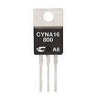
CYNA25-1000 C3 SEMI, CYNA25-1000 Datasheet

CYNA25-1000
Manufacturer Part Number
CYNA25-1000
Description
SCR THYRISTOR, 16A, 1KV, TO-220AB
Manufacturer
C3 SEMI
Datasheet
1.CYNA25-800.pdf
(2 pages)
Specifications of CYNA25-1000
Peak Repetitive Off-state Voltage, Vdrm
1kV
Gate Trigger Current Max, Igt
35mA
Current It Av
16A
On State Rms Current It(rms)
25A
Peak Non Rep Surge Current Itsm 50hz
320A
Lead Free Status / RoHS Status
Lead free / RoHS Compliant
Applications
• Motor Control
• Overvoltage Crowbar Protection
• Capacitive Discharge Ignition
• Voltage Regulation
• Welding Equipment
• Capacitive Filter Soft Start
ISO9001 Certified
TO-220AB Non-Isolated
(Inrush Current Control)
TO-220AB Isolated
K
K
(CYNA25)
(CYNB25)
A
A
G
G
G
A
K
C3 Semiconductor, LLC
A
Absolute Maximum Ratings
RMS On-State Current (full sine wave)
Average On-State Current
Non Repetitive Surge Peak On-State Current
(Full Cycle, Tj Initial = 25
I
Critical rate of rise of on-state current
I
Peak Gate Current @ T
Average Gate Power Dissipation @ Tj = 125
S
O
s I
M
Electrical Characteristics
I
V
V
I
I
dv/dt MIN @ V
V
I
I
GENERAL NOTES
2
G
GT
H
L
DRM
RRM
1. All parameters at 25 degrees C unless otherwise specified.
o t
p
GT
GD
TM
t
=2 x I
l o
x a
MAX @ I
MAX @ I
r e
a V
a r
MAX @ V
i t a
MAX @ V
MIN @ V
m i
MAX @ I
i t a
MAX @ V
MAX @ V
e g
u l
n o
u
f e
GT
g n
m
e T
o V
r o
, tr<100 ns, T
J
P
m
G
T
n u
a t l
e
u f
e p
= 1.2 I
D
=
k a
D
TM
>
>
>
>
D
i t c
e g
i s
D
=12 V, R
5
DRM =
DRM =
a r
=V
=12 V, R
0 0
Suitable for General Purpose AC Switching
IGT 40mA Max.
Isolated and Non-Isolated Tab
VDRM/VRMM 400, 600, 800, 1000V
g n
R
= 67%V
=
n o
u t
C (
v e
DRM
0 5
m
GT
e r
Y
e T
r e
V
A
, A
V
N
, R
R
e s
RRM
RRM
m
A
j
L
(
j
n a
L
p t
= 125
a g
= 125
= 30Ω
DRM
e p
˚
L
S
= 30Ω
G
) C
= 3.3kΩ
e g
=
e
e t
a r
a
i r
e t
3
o
(
u t
s e
˚
0 8
˚
a g
C
e p
C
o V
e r
s µ
n o
e t
) n
a t l
R
) y l
o
n a
e g
NOTE 1
e p
e g
) n
˚
C
Tc = 100
Tc = 75
Tc = 100
Tc = 75
Tj = 125
T
T
T
T
= j
= j
= j
= j
1
5 2
5 2
1
5 2
5 2
C ˚
C ˚
˚
°
˚
C ˚
C ˚
C
˚
°
C
C
C
C
TO-220AB Iso
TO-220AB Iso
CONDITIONS
p t
TO-220AB
TO-220AB
p t
F = 50 Hz
F
=
CYNA/CYNB25
=
=
0 6
0 1
0 2
25Amp - 400/600/800/1000V -
z H
m
s µ
s
0 1
SYMBOL
P
I
40mA
0 5
90mA
T(RMS)
V
I
I
G
0 0
4
V
1.3V
. 0
. 1
di/dt
T
µ 5
T(AV)
I
TSM
I
RGM
m
GM
T
A (
stg
ISO
m
2
V 2
V 6
/ V
j
A
t
A
A
) V
s µ
-40 to +150
-40 to +125
2500V
RATING
510A
100A/µs
320A
350A
25A
16A
1
4A
5V
W
RMS
2
s
SCR
˚
˚
C
C
Related parts for CYNA25-1000
CYNA25-1000 Summary of contents
Page 1
... Current Control) Absolute Maximum Ratings RMS On-State Current (full sine wave) Average On-State Current Non Repetitive Surge Peak On-State Current (Full Cycle, Tj Initial = Critical rate of rise of on-state current tr<100 ns TO-220AB Isolated Peak Gate Current @ T (CYNA25) Average Gate Power Dissipation @ Tj = 125 ...
Page 2
... P 0.99 1.55 0.039 0.061 Q 2.67 0.105 ISO9001 Certified Approvals UL Recognized Component - E72445 (For CYNA series) © 2007 C3 Semiconductor, All Rights Reserved. Specifications are subject to change without prior notice. C3 Semiconductor and the C3 Semiconductor logo are trademarks of C3 Semiconductor, LLC. Thermal Resistances Junction to Case (AC) ...


