VS-P135 Vishay, VS-P135 Datasheet - Page 4
VS-P135
Manufacturer Part Number
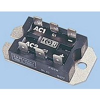
VS-P135
Description
SCR THYRISTOR, 25A, 1.2KV, D-19
Manufacturer
Vishay
Datasheet
1.P102W.pdf
(6 pages)
Specifications of VS-P135
Peak Repetitive Off-state Voltage, Vdrm
1.2kV
Gate Trigger Current Max, Igt
60mA
Current It Av
25A
Peak Non Rep Surge Current Itsm 50hz
357A
Holding Current Max Ih
130mA
Lead Free Status / RoHS Status
Lead free / RoHS Compliant


P100 Series
Vishay High Power Products
www.vishay.com
4
93754_01a
93754_02
93754_03
60
50
40
30
20
10
15
10
20
15
10
0
5
0
5
0
0
Fig. 2 - On-State Power Loss Characteristics
Fig. 3 - On-State Power Loss Characteristics
0
0
~
180°
120°
90°
60°
30°
180°
120°
Average On-State Current (A)
Average On-State Current (A)
90°
60°
30°
DC
5
Total Output Current (A)
5
5
( ine)
180°
10
+
-
10
Fig. 1 - Current Ratings Nomogram (1 Module Per Heatsink)
15
For technical questions, contact:
Conduction period
Conduction angle
10
Per junction
T
Per junction
RM limit
T
J
J
T
= 125 °C
= 125 °C
15
J
Ø
20
Ø
= 125 °C
RM limit
Passivated Assembled
Circuit Elements, 25 A
25
15
20
indmodules@vishay.com
93754_01b
93754_04
93754_05
1000
130
120
110
100
100
60
50
40
30
20
10
90
80
70
10
0
1
0
Fig. 5 - On-State Voltage Drop Characteristics
0
0
Fig. 4 - Current Ratings Characteristics
Per module
T
Instantaneous On-State Voltage (V)
J
= 25 °C
5
1
25
Ambient Temperature (°C)
Fully turned-on
Total Output Current (A)
Maximum Allowable
10
2
50
15
( ine)
3
180°
Document Number: 93754
75
(Rect.)
20
180°
T
4
Revision: 04-Nov-09
J
= 125 °C
Per junction
100
25
5
125
30
6
Related parts for VS-P135
Image
Part Number
Description
Manufacturer
Datasheet
Request
R

Part Number:
Description:
N & P CHANNEL MOSFET, 20V, SC-70
Manufacturer:
Vishay
Datasheet:
Part Number:
Description:
N & P CHANNEL MOSFET, 20V, SOIC
Manufacturer:
Vishay
Datasheet:
Part Number:
Description:
N & P CHANNEL MOSFET, 20V, TSOP
Manufacturer:
Vishay
Datasheet:

Part Number:
Description:
SCR THYRISTOR, 10A, 1.2KV, TO-208AA
Manufacturer:
Vishay
Datasheet:

Part Number:
Description:
SCR THYRISTOR, 16A, 600V, TO-208AA
Manufacturer:
Vishay
Datasheet:

Part Number:
Description:
SCR THYRISTOR, 25A, 1.2KV, TO-208AA
Manufacturer:
Vishay
Datasheet:

Part Number:
Description:
SCR THYRISTOR, 16A, 1.2KV, TO-220AB
Manufacturer:
Vishay
Datasheet:
Part Number:
Description:
SCR THYRISTOR, 16A, 50V, TO-208AA
Manufacturer:
Vishay
Datasheet:
Part Number:
Description:
SCR THYRISTOR, 16A, 400V, TO-208AA
Manufacturer:
Vishay
Datasheet:
Part Number:
Description:
SCR THYRISTOR, 16A, 800V, TO-208AA
Manufacturer:
Vishay
Datasheet:

Part Number:
Description:
SCR THYRISTOR, 50A, 1KV, TO-208AC
Manufacturer:
Vishay
Datasheet:

Part Number:
Description:
SCR THYRISTOR, 50A, 1.2KV, TO-208AC
Manufacturer:
Vishay
Datasheet:
Part Number:
Description:
SCR THYRISTOR, 50A, 600V, TO-208AC
Manufacturer:
Vishay
Datasheet:

Part Number:
Description:
THYRISTOR DIODE MOD, 25A 1.2KV D-19
Manufacturer:
Vishay
Datasheet: