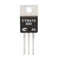
CYNB55-600PT C3 SEMI, CYNB55-600PT Datasheet

CYNB55-600PT
Manufacturer Part Number
CYNB55-600PT
Description
SCR THYRISTOR, 35A, 600V, TO-220AB
Manufacturer
C3 SEMI
Datasheet
1.CYNB55-1000.pdf
(2 pages)
Specifications of CYNB55-600PT
Peak Repetitive Off-state Voltage, Vdrm
600V
Gate Trigger Current Max, Igt
35mA
On State Rms Current It(rms)
55A
Gate Trigger Voltage Max Vgt
1.3V
Peak Reflow Compatible (260 C)
Yes
Lead Free Status / RoHS Status
Lead free / RoHS Compliant
TO-220AB Non-Isolated
Applications
• Motor Control
• Overvoltage Crowbar Protection
• Capacitive Discharge Ignition
• Voltage Regulation
• Welding Equipment
• Capacitive Filter Soft Start
ISO9001 Certified
K
(CYNB55)
A
(Inrush Current Control)
G
G
A
K
A
C3 Semiconductor, LLC
Absolute Maximum Ratings
RMS On-State Current (full sine wave)
Average On-State Current
Non Repetitive Surge Peak On-State Current
(Full Cycle, Tj Initial = 25
I
Critical rate of rise of on-state current
I
Peak Gate Current @ T
Average Gate Power Dissipation @ Tj = 125
S
O
M
Electrical Characteristics
I
V
V
I
I
dv/dt MIN @ V
V
I
I
GENERAL NOTES
2
G
GT
H
L
DRM
RRM
1. Not intented for continuous current use above 50A
2. All parameters at 25 degrees C unless otherwise specified.
o t
GT
GD
TM
p
t
=2 x I
x a
MAX @ I
MAX @ I
Continuous use obove 50A
r e
a V
a r
MAX @ V
MAX @ V
MIN @ V
m i
MAX @ I
i t a
MAX @ V
MAX @ V
e g
u l
u
GT
f e
g n
m
e T
r o
, tr<100 ns, T
J
P
m
G
T
n u
e
u f
e p
= 1.2 I
D
=
k a
D
TM
>
>
>
D
i t c
i s
=12 V, R
D
DRM =
5
DRM =
=V
a r
=12 V, R
0 0
R
Suitable for General Purpose AC Switching
IGT 35mA Max.
VDRM/VRMM 400, 600, 800, 1000V
g n
= 67%V
=
n o
u t
v e
DRM
8 7
m
GT
e r
e T
r e
RMS
V
A
, A
V
, R
R
e s
RRM
m
RRM
j
L
(
may exceed PCB solder melting temperatures.
j
L
n a
a g
p t
= 125
= 125
e p
= 30Ω
DRM
˚
L
= 30Ω
G
) C
= 3.3kΩ
e g
=
e t
a r
a
e t
3
o
(
u t
˚
0 8
˚
a g
C
e p
C
o V
e r
s µ
e t
) n
a t l
R
o
n a
e g
NOTE 2
e p
RMS
e g
) n
NOTE 1
(Fig 2); for high surge conditions only,
˚
C
Tc = 70
Tc = 70
Tj = 125
T
T
T
T
= j
= j
= j
= j
1
5 2
5 2
1
5 2
5 2
C ˚
C ˚
˚
°
˚
C ˚
C ˚
C
C
C
TO-220AB
CONDITIONS
p t
TO-220AB
p t
F = 50 Hz
F
=
=
=
0 6
0 1
0 2
55Amp - 400/600/800/1000V -
z H
m
s µ
s
0 1
SYMBOL
P
I
35mA
0 5
90mA
T(RMS)
I
V
I
G
0 0
4
di/dt
1.3V
. 0
. 1
µ 5
T(AV)
I
T
I
TSM
RGM
2
GM
m
T
A (
stg
m
V 2
V 6
t
/ V
j
A
A
CYNB55
A
) V
s µ
-40 to +150
-40 to +125
RATING
2030A
100A/µs
675A
700A
55A
35A
1
4A
5V
W
2
SCR
s
˚
˚
C
C
Related parts for CYNB55-600PT
CYNB55-600PT Summary of contents
Page 1
... D DRM = µ ˚ ˚ DRM = RRM ˚ DRM = RRM (Fig 2); for high surge conditions only, RMS may exceed PCB solder melting temperatures. RMS CYNB55 55Amp - 400/600/800/1000V - SCR CONDITIONS SYMBOL RATING TO-220AB I 55A T(RMS) I TO-220AB 35A T(AV 675A I TSM 700A 2030A 2 s di/dt 100A/µ ...
Page 2
... For recommended applications and more information contact: For recommended applications and more information contact: USA : Sales Support USA : Sales Support (888) 882-8689 C3 Semiconductors, LLC. 2320 Paseo de las Americas, Ste. 104, San Diego, CA 92154 Email : sales@c3semi.com WEB SITE: http://www.C3semi.com CYNB55 55Amp - 400/600/800/1000V - SCR SYMBOL RATING ˚ ...


