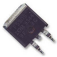
VS-15ETH06SPBF Vishay, VS-15ETH06SPBF Datasheet

VS-15ETH06SPBF
Specifications of VS-15ETH06SPBF
Available stocks
Related parts for VS-15ETH06SPBF
VS-15ETH06SPBF Summary of contents
Page 1
... 150 ° rated 150 ° rated 600 V R Measured lead to lead 5 mm from package body For technical questions, contact: diodes-tech@vishay.com Vishay High Power Products RoHS* COMPLIANT MAX. UNITS 600 V 15 120 175 °C MIN. TYP. MAX. UNITS 600 - - - 1.8 2 ...
Page 2
... 125 ° ° 125 ° 125 °C di /dt = 800 A/µ 390 V R TEST CONDITIONS Typical socket mount Mounting surface, flat, smooth and greased 2 Case style D PAK Case style TO-262 For technical questions, contact: diodes-tech@vishay.com MIN. TYP. MAX. UNITS - 3 µC - 300 ...
Page 3
... Vishay High Power Products 1000 T = 175 °C J 100 T = 150 ° 125 ° 100 °C J 0.1 0. °C J 0.001 0 100 200 300 400 500 V - Reverse Voltage (V) R Fig Typical Values of Reverse Current vs. Reverse Voltage 500 600 Notes: 1. Duty factor Peak thJC Characteristics thJC www.vishay.com 600 ...
Page 4
... R1 R For technical questions, contact: diodes-tech@vishay.com 100 390 125 ° ° 100 di /dt (A/µs) F Fig Typical Reverse Recovery Time vs. di 1000 V = 390 125 ° °C 800 600 400 200 0 100 di /dt (A/µs) F Fig Typical Stored Charge vs. di Document Number: 94003 Revision: 17-Apr-07 ...
Page 5
... F ( area under curve defined and I RRM (5) di (rec)M current during t to point where a line passing and 0.50 I RRM RRM Fig Reverse Recovery Waveform and Definitions For technical questions, contact: diodes-tech@vishay.com Vishay High Power Products ( 0.5 I RRM (5) di /dt (rec)M RRM ...
Page 6
... Thermal pad contour optional within dimension E, L1, D1 and E1 - (4) Dimension b1 and c1 apply to base metal only - (5) Controlling dimension: inches (6) 0.028 Outline conform to JEDEC TO-262 except A1 (maximum), b (minimum) and D1 (minimum) where dimensions derived the 93° actual package outline For technical questions, contact: diodes-tech@vishay.com Seating plane ...
Page 7
... Hyperfast Rectifier P 2 4.0 ± 0.1 C See note ( 10.50 ± 0.1 0.35 ± 0.05 0.12 MAX 1. 4.90 ± 0.1 Section Ω per square. Measured in accordance to procedure given in 6 For technical questions, contact: diodes-tech@vishay.com Vishay High Power Products www.vishay.com C 1.75 ± 0 ...
Page 8
... None = Tube (50 pieces) 6 TRL = Tape and reel (left oriented, for D TRR = Tape and reel (right oriented, for None = Standard production PbF = Lead (Pb)-free For technical questions, contact: diodes-tech@vishay.com Part Number 15ETH06-1 002P Date Code 80 24 Year 0 = 2000 Week Lead (Pb)-free TRL PbF ...
Page 9
... Except as provided in Vishay's terms and conditions of sale for such products, Vishay assumes no liability whatsoever, and disclaims any express or implied warranty, relating to sale and/or use of Vishay products including liability or warranties relating to fitness for a particular purpose, merchantability, or infringement of any patent, copyright, or other intellectual property right. ...


