2N3906-AP Micro Commercial Components (MCC), 2N3906-AP Datasheet
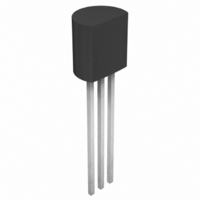
200mA, 40V 600mW PNP Transistor, TO-92 / AMMO

2N3906-AP

Manufacturer Part Number
2N3906-AP
Description
200mA, 40V 600mW PNP Transistor, TO-92 / AMMO
Manufacturer
Micro Commercial Components (MCC)
Type
Amplifier, Medium Powerr
Datasheets

Specifications of 2N3906-AP

Transistor Type
PNP
Current - Collector (ic) (max)
200mA
Voltage - Collector Emitter Breakdown (max)
40V
Vce Saturation (max) @ Ib, Ic
400mV @ 5mA, 50mA
Dc Current Gain (hfe) (min) @ Ic, Vce
100 @ 10mA, 1V
Power - Max
600mW
Frequency - Transition
250MHz
Mounting Type
Through Hole
Package / Case
TO-92
Current, Collector
200 mA
Current, Gain
100
Frequency
250 MHz
Package Type
TO-92
Polarity
PNP
Power Dissipation
600 mW
Primary Type
Si
Voltage, Breakdown, Collector To Emitter
40 V
Voltage, Collector To Base
40 V
Voltage, Collector To Emitter
40 V
Voltage, Collector To Emitter, Saturation
0.4 V
Voltage, Emitter To Base
5 V
Transistor Polarity
PNP
Collector Emitter Voltage V(br)ceo
40V
Power Dissipation Pd
600mW
Dc Collector Current
200mA
Dc Current Gain Hfe
30
No. Of Pins
3
Rohs Compliant
Yes
Lead Free Status / RoHS Status
Lead free / RoHS Compliant
Current - Collector Cutoff (max)
-
Lead Free Status / Rohs Status
RoHS Compliant part
Other names
2N3906-APTB
Features
Revision: A
Micro Commercial Components
Electrical Characteristics @ 25°C Unless Otherwise Specified
OFF CHARACTERISTICS
ON CHARACTERISTICS
SMALL-SIGNAL CHARACTERISTICS
SWITCHING CHARACTERISTICS
*Pulse Width ≤ 300µs, Duty Cycle ≤ 2.0%
V
V
V
I
I
h
V
V
f
C
C
NF
t
t
t
t
BL
CEX
T
d
r
s
f
Symbol
FE
(BR)CEO
(BR)CBO
(BR)EBO
CE(sat)
BE(sat)
obo
ibo
RoHS Compliant. See ordering information)
M C C
Capable of 600mW of Power Disspation and 200mA Ic
Epoxy meets UL 94 V-0 flammability rating
Moisure Sensitivity Level 1
Through Hole Package
Marking:Type number
Lead Free Finish/RoHS Compliant ("P" Suffix designates
Collector-Emitter Breakdown Voltage*
Collector-Base Breakdown Voltage
Emitter-Base Breakdown Voltage
Base Cutoff Current
Collector Cutoff Current
DC Current Gain*
Collector-Emitter Saturation Voltage
Current Gain-Bandwidth Product
Output Capacitance
Input Capacitance
(V
(I
f=10Hz to 15.7kHz)
Base-Emitter Saturation Voltage
Noise Figure
Delay Time
Rise Time
Storage Time
Fall Time
C
(I
(I
(I
(V
(V
(I
(I
(I
(I
(I
(I
(I
(I
(I
(I
(V
BE
=100µAdc, V
C
C
E
C
C
C
C
C
C
C
C
C
C
=1.0mAdc, I
=10µAdc, I
=10µAdc, I
CE
CE
=0.1mAdc, V
=1.0mAdc, V
=10mAdc, V
=50mAdc, V
=100mAdc, V
=10mAdc, I
=50mAdc, I
=10mAdc, I
=50mAdc, I
=10mAdc, V
CB
=0.5Vdc, I
=30Vdc, V
=30Vdc, V
=5.0Vdec, I
C
Parameter
C
E
=0, f=100kHz)
CE
B
B
B
B
=0)
=0)
B
BE
BE
CE
CE
CE
=1.0mAdc)
=5.0mAdc)
=1.0mAdc)
=5.0mAdc)
=0)
CE
CE
E
=5.0Vdc, R
CE
(V
(V
I
I
=3.0Vdc)
=3.0Vdc)
=1.0Vdc)
=1.0Vdc)
=20Vdc, f=100MHz)
=0, f=100MHz)
C
B1
=1.0Vdc)
=1.0Vdc)
=1.0Vdc)
=10mAdc, I
CC
CC
=I
www.mccsemi.com
=3.0Vdc, V
=3.0Vdc, I
B2
TM
=1.0mAdc)
S
=1.0kΩ
  omponents
20736 Marilla Street Chatsworth

  !"#
$ %    !"#
B1
C
=1.0mAdc)
BE
=10mAdc
=0.5Vdc
0.65
Min
100
5.0
250
40
40
60
80
60
30
Max
0.25
0.85
0.95
10.0
300
225
0.4
4.5
4.0
50
50
35
35
75
1 of 5
Units
nAdc
nAdc
MHz
Vdc
Vdc
Vdc
Vdc
Vdc
dB
pF
pF
ns
ns
ns
ns
DIM
A
B
C
D
E
G
Purpose Amplifier
MIN
.170
.170
.550
.010
.130
.096
PNP General
A
G
INCHES
2N3906
D
MAX
.190
.190
.590
.020
.160
.104
TO-92
DIMENSIONS
13.97
4.33
4.30
0.36
3.30
2.44
MIN
C
E
B
B
MM
C
14.97
MAX
4.83
4.83
0.56
3.96
2.64
2011/01/01
E
NOTE

Related parts for 2N3906-AP

2N3906-AP Summary of contents

Page 1

... S =0.5Vdc 35 BE =1.0mAdc =10mAdc 225 C =1.0mAdc 2N3906 PNP General Purpose Amplifier TO-92 Units A Vdc Vdc Vdc nAdc nAdc Vdc D Vdc MHz G pF DIMENSIONS pF INCHES DIM MIN MAX dB A .170 ...

Page 2

... DC Current Gain vs Collector Current 220 200 160 h FE 120 80 40 0.1 1 Collector-Emitter Saturation Volatge vs Collector Current 0.6 0.5 0 (V) CE(SAT) 0.3 0.2 0.1 0 1.0 10 Collector-Base Diode Reverse Current vs Temperature 100 V = 20V (mA) CBO 1.0 0 www.mccsemi.com Revision 1. BE(ON) 10 100 I (mA 25° (V) BE(SAT) ...

Page 3

... Maximum Power Dissipation vs Ambient Temperature 800 600 P - (mW) D(MAX) 400 200 SOT- Contours of Constant Gain Bandwidth Product ( ( 0.1 1.0 I *100MHz increments from 100 to 700, 750 and 800MHz Noise Figure vs Frequency (dB 0.1 1.0 www.mccsemi.com Revision: A TO- (dB) 100 150 200 - (° 100 ...

Page 4

... Input Impedance (kΩ) ie 1.0 0.1 0.1 Voltage Feedback Ratio 100 - (X10 ) fe 10 1.0 0.1 www.mccsemi.com Revision 10V 1.0kHz h - (µΩ (mA (ns) 1 (mA Micro Commercial Components Output Admittance 1000 V = 10V 1.0kHz 100 10 0.1 1 (mA) C Turn On and Turn Off Times vs Collector Current ...

Page 5

... MCC's products are not authorized for use as critical components in life support devices or systems without the express written Counterfeiting of semiconductor parts is a growing problem in the industry. Micro Commercial Components (MCC) is taking strong measures to protect ourselves and our customers from the proliferation of counterfeit parts. MCC strongly encourages customers to purchase MCC parts either directly from MCC or from Authorized MCC Distributors who are listed by country on our web page cited below ...

Related keywords