MAT03FH Analog Devices Inc, MAT03FH Datasheet - Page 8
MAT03FH
Manufacturer Part Number
MAT03FH
Description
Transistor
Manufacturer
Analog Devices Inc
Datasheet
1.MAT03FHZ.pdf
(12 pages)
Specifications of MAT03FH
Rohs Status
RoHS non-compliant
Transistor Type
2 PNP (Dual)
Current - Collector (ic) (max)
20mA
Voltage - Collector Emitter Breakdown (max)
36V
Vce Saturation (max) @ Ib, Ic
100mV @ 100µA, 1mA
Power - Max
500mW
Frequency - Transition
190MHz
Mounting Type
Through Hole
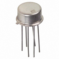
Package / Case
TO-78-6 Metal Can
Current - Collector Cutoff (max)
-
Dc Current Gain (hfe) (min) @ Ic, Vce
-
Lead Free Status / RoHS Status


MAT03
This amplifier exhibits excellent full power ac performance,
0.08% THD into a 600 Ω load, making it suitable for exacting
audio applications (see Figure 3b).
LOW NOISE MICROPHONE PREAMPLIFIER
Figure 4 shows a microphone preamplifier that consists of a
MAT03 and a low noise op amp. The input stage operates at a
relatively high quiescent current of 2 mA per side, which reduces
the MAT03 transistor’s voltage noise. The 1/ƒ corner is less than
1 Hz. Total harmonic distortion is under 0.005% for a 10 V p-p
signal from 20 Hz to 20 kHz. The preamp gain is 100, but can be
modified by varying R
A total input stage emitter current of 4 mA is provided by Q
The constant current in Q
a GaAsP LED as a reference. The difference between this voltage
5
or R
2
is set by using the forward voltage of
6
(V
OUT
/V
IN
= R
5
/R
6
+ 1).
2
.
and the V
a few percent) over a wide temperature range. The voltage differ-
ence, approximately 1 V, is dropped across the 250 Ω resistor
which produces a temperature stabilized emitter current.
CURRENT SOURCES
A fundamental requirement for accurate current mirrors and
active load stages is matched transistor components. Due to the
excellent V
required to equalize collector current) and gain matching, the
MAT03 can be used to implement a variety of standard current
mirrors that can source current into a load such as an amplifier
stage. The advantages of current loads in amplifiers versus
resistors is an increase of voltage gain due to higher imped-
ances, larger signal range, and in many applications a wider
signal bandwidth.
Figure 5 illustrates a cascode current mirror consisting of two
MAT03 transistor pairs.
The cascode current source has a common base transistor in se-
ries with the output which causes an increase in output imped-
ance of the current source since V
High frequency characteristics are improved due to a reduction
of Miller capacitance. The small-signal output impedance can
be determined by consulting “h
graph. Typical output impedance levels approach the perfor-
mance of a perfect current source.
Considering a typical collector current of 100 µA, we have:
BE
BE
of a silicon transistor is predictable and constant (to
matching (the voltage difference between V
ro
Q3
=
1.0 µ MHOS
1
OF
CE
vs. Collector Current” typical
= 1 MΩ
stays relatively constant.
BE
s
Related parts for MAT03FH
Image
Part Number
Description
Manufacturer
Datasheet
Request
R

Part Number:
Description:
±1.7g Dual-Axis IMEMS Accelerometer Evaluation Board
Manufacturer:
Analog Devices Inc
Datasheet:

Part Number:
Description:
Inertial Sensor Evaluation System
Manufacturer:
Analog Devices Inc
Datasheet:
Part Number:
Description:
Manufacturer:
Analog Devices Inc
Datasheet:
Part Number:
Description:
Manufacturer:
Analog Devices Inc
Datasheet:
Part Number:
Description:
Manufacturer:
Analog Devices Inc
Datasheet:
Part Number:
Description:
Manufacturer:
Analog Devices Inc
Datasheet:
Part Number:
Description:
Manufacturer:
Analog Devices Inc
Datasheet:
Part Number:
Description:
Manufacturer:
Analog Devices Inc
Datasheet:
Part Number:
Description:
Manufacturer:
Analog Devices Inc
Datasheet:
Part Number:
Description:
Manufacturer:
Analog Devices Inc
Datasheet:
Part Number:
Description:
Manufacturer:
Analog Devices Inc
Datasheet:
Part Number:
Description:
Manufacturer:
Analog Devices Inc
Datasheet:
Part Number:
Description:
Manufacturer:
Analog Devices Inc
Datasheet: