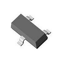
MMBZ4714-V-GS18 Vishay, MMBZ4714-V-GS18 Datasheet - Page 3

MMBZ4714-V-GS18
Manufacturer Part Number
MMBZ4714-V-GS18
Description
Zener Diode,Single, Two Terminal,33V V(Z),5%,SOT-23
Manufacturer
Vishay
Datasheet
1.MMBZ4694-V-GS08.pdf
(6 pages)
Specifications of MMBZ4714-V-GS18
Zener Voltage
33 V
Voltage Tolerance
5 %
Power Dissipation
350 mW
Maximum Reverse Leakage Current
10 nA
Maximum Operating Temperature
+ 150 C
Mounting Style
SMD/SMT
Minimum Operating Temperature
- 55 C
Voltage Regulation Accuracy
330 mV
Package / Case
SOT-23
Lead Free Status / RoHS Status
Lead free / RoHS Compliant
Typical Characteristics
Document Number 85771
Rev. 1.6, 15-Sep-10
Figure 2. Typical Change of Working Voltage under Operating
Figure 1. Total Power Dissipation vs. Ambient Temperature
Figure 3. Typical Change of Working Voltage vs.
95 9602
95 9599
95 9598
1000
100
600
500
400
300
200
100
1.3
1.2
1.1
1.0
0.9
0.8
10
1
0
Conditions at T
- 60
0
0
Junction Temperature
T
T
V
j
T
= 25 °C
Ztn
amb
j
- Junction Temperature (°C)
40
DiodesAmericas@vishay.com, DiodesAsia@vishay.com,
= V
0
5
- Ambient Temperature (°C)
Zt
V
For technical questions within your region, please contact one of the following:
/V
Z
- Z-Voltage (V)
Z
80
10
60
(25 °C)
amb
TK
VZ
I
(T
Z
= 10 x 10
= 25 °C
= 5 mA
120
120
amb
15
-4
/K
= 25 °C, unless otherwise specified)
160
180
- 2 x 10
- 4 x 10
20
8 x 10
6 x 10
4 x 10
2 x 10
0
-4
-4
-4
-4
-4
-4
200
/K
/K
240
/K
/K
/K
/K
25
MMBZ4681-V to MMBZ4717-V
Figure 4. Temperature Coefficient of V
Figure 6. Forward Current vs. Forward Voltage
95 9600
95 9605
Figure 5. Diode Capacitance vs. Z-Voltage
95 9601
0.001
DiodesEurope@vishay.com
0.01
100
200
150
100
0.1
- 5
10
15
10
50
5
0
1
0
0
0
0
0.2
V
10
5
F
V
- Forward Voltage (V)
V
T
Z
Vishay Semiconductors
j
Z
- Z-Voltage (V)
= 25 °C
- Z-Voltage (V)
0.4
20
10
I
Z
= 5 mA
0.6
30
15
T
V
j
R
= 25 °C
Z
40
= 2 V
0.8
20
vs. Z-Voltage
www.vishay.com
1.0
50
25
3


