VSKC250-08 Vishay, VSKC250-08 Datasheet - Page 10
VSKC250-08
Manufacturer Part Number
VSKC250-08
Description
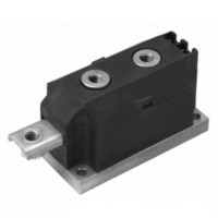
800V MAGN-A-Pak
Manufacturer
Vishay
Datasheet
1.VSKE320-04.pdf
(12 pages)
Specifications of VSKC250-08
Current - Reverse Leakage @ Vr
50mA @ 800V
Current - Average Rectified (io) (per Diode)
250A
Voltage - Dc Reverse (vr) (max)
800V
Diode Type
Standard
Speed
Standard Recovery >500ns, > 200mA (Io)
Diode Configuration
1 Pair Common Cathode
Mounting Type
Chassis Mount
Package / Case
3-MAGN-A-PAK™
Product
Standard Recovery Rectifier
Configuration
Dual Common Cathode
Reverse Voltage
800 V
Forward Voltage Drop
1.29 V
Forward Continuous Current
250 A
Max Surge Current
7345 A
Reverse Current Ir
50000 uA
Mounting Style
Screw
Maximum Operating Temperature
+ 150 C
Minimum Operating Temperature
- 40 C
Lead Free Status / RoHS Status
Lead free / RoHS Compliant
Reverse Recovery Time (trr)
-
Voltage - Forward (vf) (max) @ If
-
Lead Free Status / RoHS Status
Lead free / RoHS Compliant
Other names
*IRKC250-08
IRKC250-08
IRKC250-08
IRKC250-08
IRKC250-08


VSK.250, VSK.270, VSK.320 Series
Vishay Semiconductors
www.vishay.com
10
Fig. 30 - Maximum Non-Repetitive Surge Current
Fig. 31 - Maximum Non-Repetitive Surge Current
10000
10000
9000
8000
7000
6000
5000
4000
3000
2000
9000
8000
7000
6000
5000
4000
3000
2000
Numb er Of Equal Amplitude Half Cyc le Current Pulses (N)
0.01
1
At Any Ra ted Load Condition And With
Ma ximum Non Rep etitive Surge Current
VSK.320.. Series
Per Junc tion
Rated V
VSK.320.. S eries
Per Junc tio n
Pulse T rain Dura tion (s)
R RM
Versus Pulse T rain Dura tion.
DiodesAmericas@vishay.com, DiodesAsia@vishay.com,
2800
2400
2000
1600
1200
Rated V
No Vo ltage Reap plied
App lied Following S urge.
800
400
For technical questions within your region, please contact one of the following:
0.1
0
10
0
Initial T = 150°C
Initial T = 150°C
@ 60 Hz 0.0083 s
@ 50 Hz 0.0100 s
R RM
200
Reap plied
T otal Output Current (A)
J
J
Standard Recovery Diodes, 250 A to 320 A
400
Fig. 29 - Forward Power Loss Characteristics
100
1
(Rec t)
(MAGN-A-PAK Power Modules)
3 x VSK.320.. Series
T hree Phase Bridge
120°
600
Connected
T = 150°C
J
800
1000
0
Maximum Allowable Ambient T emperature (°C)
25
50
Fig. 33 - Thermal Impedance Z
10000
0.001
Fig. 32 - Forward Voltage Drop Characteristics
DiodesEurope@vishay.com
1000
0.01
100
0.1
75
0.001
1
0.5
S teady S tate Value:
R
(DC Operation)
Instantaneous Forward Voltage (V)
thJC
100
T = 25°C
S quare Wave Pulse Duration (s )
1
J
0.01
= 0.45 K/ W
125
1.5
0.1
2
150
VSK.320.. S eries
Per Junc tion
VSK.320.. S eries
Per Junction
2.5
1
thJC
Document Number: 93581
T = 150°C
3
J
10
Characteristics
3.5
Revision: 02-Jul-10
100
4
Related parts for VSKC250-08
Image
Part Number
Description
Manufacturer
Datasheet
Request
R

Part Number:
Description:
1200V MAGN-A-Pak
Manufacturer:
Vishay
Datasheet:
Part Number:
Description:
1600V MAGN-A-Pak
Manufacturer:
Vishay
Datasheet:

Part Number:
Description:
357-036-542-201 CARDEDGE 36POS DL .156 BLK LOPRO
Manufacturer:
Vishay
Datasheet:
Part Number:
Description:
357-036-542-201 CARDEDGE 36POS DL .156 BLK LOPRO
Manufacturer:
Vishay
Datasheet:
Part Number:
Description:
357-036-542-201 CARDEDGE 36POS DL .156 BLK LOPRO
Manufacturer:
Vishay
Datasheet:
Part Number:
Description:
357-036-542-201 CARDEDGE 36POS DL .156 BLK LOPRO
Manufacturer:
Vishay
Datasheet:
Part Number:
Description:
357-036-542-201 CARDEDGE 36POS DL .156 BLK LOPRO
Manufacturer:
Vishay
Datasheet:
Part Number:
Description:
357-036-542-201 CARDEDGE 36POS DL .156 BLK LOPRO
Manufacturer:
Vishay
Datasheet:
Part Number:
Description:
357-036-542-201 CARDEDGE 36POS DL .156 BLK LOPRO
Manufacturer:
Vishay
Datasheet:
Part Number:
Description:
357-036-542-201 CARDEDGE 36POS DL .156 BLK LOPRO
Manufacturer:
Vishay
Datasheet:
Part Number:
Description:
357-036-542-201 CARDEDGE 36POS DL .156 BLK LOPRO
Manufacturer:
Vishay
Datasheet:
Part Number:
Description:
357-036-542-201 CARDEDGE 36POS DL .156 BLK LOPRO
Manufacturer:
Vishay
Datasheet:
Part Number:
Description:
357-036-542-201 CARDEDGE 36POS DL .156 BLK LOPRO
Manufacturer:
Vishay
Datasheet:
Part Number:
Description:
357-036-542-201 CARDEDGE 36POS DL .156 BLK LOPRO
Manufacturer:
Vishay
Datasheet:
Part Number:
Description:
357-036-542-201 CARDEDGE 36POS DL .156 BLK LOPRO
Manufacturer:
Vishay
Datasheet: