VSKD600-08 Vishay, VSKD600-08 Datasheet - Page 2
VSKD600-08
Manufacturer Part Number
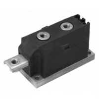
VSKD600-08
Description
800V Doubler Super MAGN-A-Pak
Manufacturer
Vishay
Datasheet
1.VSKD600-08.pdf
(7 pages)
Specifications of VSKD600-08
Voltage - Forward (vf) (max) @ If
1.24V @ 1800A
Current - Reverse Leakage @ Vr
50mA @ 800V
Current - Average Rectified (io) (per Diode)
600A
Voltage - Dc Reverse (vr) (max)
800V
Diode Type
Standard
Speed
Standard Recovery >500ns, > 200mA (Io)
Diode Configuration
1 Pair Series Connection
Mounting Type
Chassis Mount
Package / Case
3-MAGN-A-PAK™
Product
Standard Recovery Rectifier
Configuration
Dual Series
Reverse Voltage
800 V
Forward Voltage Drop
1.45 V at 1800 A
Forward Continuous Current
600 A
Max Surge Current
20100 A
Reverse Current Ir
50000 uA
Mounting Style
Screw
Maximum Operating Temperature
+ 150 C
Minimum Operating Temperature
- 40 C
Lead Free Status / RoHS Status
Lead free / RoHS Compliant
Reverse Recovery Time (trr)
-
Lead Free Status / RoHS Status
Lead free / RoHS Compliant
Other names
*IRKD600-08
IRKD600-08
IRKD600-08
IRKD600-08
IRKD600-08


VSKD600 Series
Vishay Semiconductors
www.vishay.com
2
FORWARD CONDUCTION
PARAMETER
Maximum average forward current
at case temperature
Maximum RMS forward current
Maximum peak, one-cycle forward,
non-repetitive surge current
Maximum I
Maximum I
Low level value of threshold voltage
High level value of threshold voltage
Low level value of forward slope resistance
High level value of forward slope resistance
Maximum forward voltage drop
BLOCKING
PARAMETER
RMS insulation voltage
Maximum peak reverse and
off-state leakage current
THERMAL AND MECHANICAL SPECIFICATIONS
PARAMETER
Maximum junction operating and storage
temperature range
Maximum thermal resistance,
junction to case per junction
Maximum thermal resistance,
case to heatsink
Mounting torque
± 10 %
Approximate weight
Case style
2
2
t for fusing
t for fusing
SMAP to heatsink
busbar to SMAP
DiodesAmericas@vishay.com, DiodesAsia@vishay.com,
For technical questions within your region, please contact one of the following:
(SUPER MAGN-A-PAK Power Modules)
SYMBOL
SYMBOL
SYMBOL
T
R
V
V
I
R
F(RMS)
J
I
I
I
V
F(TO)1
F(TO)2
V
thC-hs
F(AV)
I
RRM
, T
FSM
I
2
r
r
thJC
INS
2
FM
f1
f2
t
t
Stg
Standard Diodes, 600 A
180° conduction, half sine wave
180° conduction, half sine wave at T
t = 10 ms
t = 8.3 ms
t = 10 ms
t = 8.3 ms
t = 10 ms
t = 8.3 ms
t = 10 ms
t = 8.3 ms
t = 0.1 ms to 10 ms, no voltage reapplied
(16.7 % x x I
(I > x I
(16.7 % x x I
(I > x I
I
t = 1 s
T
DC operation
A mounting compound is recommended and the torque
should be rechecked after a period of 3 hours to allow
for the spread of the compound.
See dimensions - link at the end of datasheet
pk
J
= T
= 1800 A, T
J
maximum, rated V
F(AV)
F(AV)
), T
), T
No voltage
reapplied
100 % V
reapplied
No voltage
reapplied
100 % V
reapplied
F(AV)
F(AV)
J
J
J
= 25 °C, t
TEST CONDITIONS
TEST CONDITIONS
= T
= T
TEST CONDITIONS
< I < x I
< I < x I
J
J
maximum
maximum
RRM
RRM
p
RRM
DiodesEurope@vishay.com
= 10 ms sine pulse
F(AV)
F(AV)
applied
Sinusoidal half wave,
initial T
), T
), T
J
J
C
= T
= T
J
= 100 °C
= T
J
J
maximum
maximum
J
maximum
Document Number: 93583
- 40 to 150
SUPER MAGN-A-PAK
VALUES
VALUES
VALUES
12 to 15
18 050
0.065
6 to 8
3000
1805
1683
1319
1230
1500
19.0
20.1
16.2
17.2
0.70
0.77
0.28
0.25
1.45
0.02
600
100
942
50
Revision: 02-Jul-10
UNITS
UNITS
UNITS
kA
kA
K/W
m
mA
Nm
°C
kA
°C
A
A
V
V
V
g
2
2
s
s
Related parts for VSKD600-08
Image
Part Number
Description
Manufacturer
Datasheet
Request
R

Part Number:
Description:
1200V Doubler Super MAGN-A-Pak
Manufacturer:
Vishay
Datasheet:
Part Number:
Description:
1600V Doubler Super MAGN-A-Pak
Manufacturer:
Vishay
Datasheet:
Part Number:
Description:
2000V Doubler Super MAGN-A-Pak
Manufacturer:
Vishay
Datasheet:

Part Number:
Description:
Standard Diodes
Manufacturer:
Vishay Siliconix
Datasheet:

Part Number:
Description:
357-036-542-201 CARDEDGE 36POS DL .156 BLK LOPRO
Manufacturer:
Vishay
Datasheet:
Part Number:
Description:
357-036-542-201 CARDEDGE 36POS DL .156 BLK LOPRO
Manufacturer:
Vishay
Datasheet:
Part Number:
Description:
357-036-542-201 CARDEDGE 36POS DL .156 BLK LOPRO
Manufacturer:
Vishay
Datasheet:
Part Number:
Description:
357-036-542-201 CARDEDGE 36POS DL .156 BLK LOPRO
Manufacturer:
Vishay
Datasheet:
Part Number:
Description:
357-036-542-201 CARDEDGE 36POS DL .156 BLK LOPRO
Manufacturer:
Vishay
Datasheet:
Part Number:
Description:
357-036-542-201 CARDEDGE 36POS DL .156 BLK LOPRO
Manufacturer:
Vishay
Datasheet:
Part Number:
Description:
357-036-542-201 CARDEDGE 36POS DL .156 BLK LOPRO
Manufacturer:
Vishay
Datasheet:
Part Number:
Description:
357-036-542-201 CARDEDGE 36POS DL .156 BLK LOPRO
Manufacturer:
Vishay
Datasheet:
Part Number:
Description:
357-036-542-201 CARDEDGE 36POS DL .156 BLK LOPRO
Manufacturer:
Vishay
Datasheet:
Part Number:
Description:
357-036-542-201 CARDEDGE 36POS DL .156 BLK LOPRO
Manufacturer:
Vishay
Datasheet:
Part Number:
Description:
357-036-542-201 CARDEDGE 36POS DL .156 BLK LOPRO
Manufacturer:
Vishay
Datasheet: