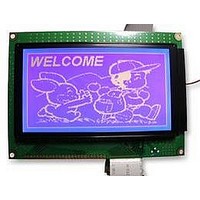
LMR4234EW-WCB DENSITRON, LMR4234EW-WCB Datasheet - Page 17

LMR4234EW-WCB
Manufacturer Part Number
LMR4234EW-WCB
Description
LCD MODULE, 128X240, BLUE
Manufacturer
DENSITRON
Datasheet
1.LMR4234EW-WCB.pdf
(51 pages)
Specifications of LMR4234EW-WCB
Lcd Display Type
STN
Pixel Size (h X W)
0.43mm X 0.43mm
Interface Type
Serial
Viewing Area (h X W)
64mm X 114mm
Supply Voltage
5V
External Depth
14.3mm
External Length /
RoHS Compliant
Display Mode
Transmissive
Svhc
No SVHC (15-Dec-2010)
Rohs Compliant
Yes
Backlighting Colour
White
Pixel Pitch (h X W)
0.45mm X 0.45mm
BIT SET/RESET
Setting registers
(1)Set Cursor Pointer
(2)Set Offset Register
00100001
00100010
00100100
CODE
The position of the cursor is specified by X ADRS and Y ADRS. The cursor position can only be
moved by this command. Data read/write from the MPU never changes the cursor pointer. X ADRS
and Y ADRS are specified as follows.
Single-Scan
X ADRS 00 to 4FH
The offset register is used to determine the external character generator RAM area.
The T6963C has a 16-bit address bus as follows.
X ADRS 00H to 4FH (lower 7 bits are valid)
Y ADRS 00H to 1FH (lower 5 bits are valid)
DENSITRON TECHNOLOGIES plc. – PROPRIETARY DATA – ALL RIGHTS RESERVED
Y ADRS 00H to 0FH
HEX.
21H
23H
24H
11111×001
11111×010
11111×011
11111×100
11111×101
11111×110
11111×111
11110×××
11111×××
1111×000
SET CURSOR POINTER
SET OFFSET REGISTER
SET ADDRESS POINTER
FUNCTION
-
-
-
-
-
-
-
-
-
-
-
-
-
-
-
-
-
-
-
-
LOW ADRS HIGH ADRS
X ADRS
Bit Reset
Bit Set
Bit 0 (LSB)
Bit 1
Bit 2
Bit 3
Bit 4
Bit 5
Bit 6
Bit 7 (MSB)
DATA
D1
Y ADRS
00H
D2
Page
X: invalid
17 / 51


