PG12864LRF-NRA-H-Q POWERTIP, PG12864LRF-NRA-H-Q Datasheet - Page 24
PG12864LRF-NRA-H-Q
Manufacturer Part Number
PG12864LRF-NRA-H-Q
Description
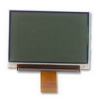
LCD MODULE, 128X64, LED B/L
Manufacturer
POWERTIP
Datasheet
1.PG12864LRF-NRA-H-Q.pdf
(29 pages)
Specifications of PG12864LRF-NRA-H-Q
Lcd Display Type
FSTN
Pixel Size (h X W)
0.28mm X 0.34mm
Viewing Area (h X W)
45.2mm X 27mm
Supply Voltage
3.3V
External Depth
6mm
External Length / Height
39mm
External
RoHS Compliant
Display Mode
Transflective


2.5.5
2.5.6
2.5.4-3
Display Starting Line Register
Addressing of Display RAM
Display RAM consists of 128 x 64 bit memory, and makes access in 8 bit unit to an address specified
by X address and Y address from MPU.
The address, X and Y are possible to be set up so that can increment automatically with the address
control register. The increment is made every time Display RAM is read or written from MPU.
Thought the X direction side is selected by X address while the Y direction side by Y address,
10H-FFH in the X address are inhibited and do not have the X address set in these addresses.
In the Y direction side, the 128-bit display data are internally read the display data latch circuit at the
rising of LP every one line cycle, and are output from the display data latch circuit at the falling of
LP.
This register is for determining display start line (usually the most upper line)
Corresponding to COM0 in case of display the Display data RAM.
The register is also used in picture-scrolling.
The 6-bit display starting address is set in this register by display starting-line setting command.
The register are preset every timing of FLM signal variation in the display line counter. The line
counter counts up being synchronized with LP input and generates line addressed which read out
sequentially 128-bit data from Display RAM to LCD driver circuit.
Segment Display mode and Graphic Display mode are independent of each other.
When using Segment Display mode, low current consumption mode available.
When using Stave mode, please input clock for Segment Display at WXA terminal.
(500Hz:Duty 50%)and this time , EXA Flag (EH register : Power control(3) register) must be fixed
“H”.
ICON Display Mode
This mode enable 2 output terminal for icon Display and 1 icon.
Source are VDD and VSS. Since this mode independent of other mode completely, When specified
this mode, lower current consumption mode is set.
When Display, used to internal Clock or external Clock is selectable.
When Display , used to internal Clock or external Clock is selectable.
When using external Clock , and please input clock pulse to EXA terminal (120 Hz : Duty 50%:
When using icon display and Segment display , please input 500Hz Duty 50%
ICON1
X address are 00H-01H, and Y address are 40H-42H.
DISPLAY DEVICES FOR BETTER ELECTRONIC DESIGN
POWERTIP TECHNOLOGY CORPORATION
VDD
VSS
VDD
VSS
Related parts for PG12864LRF-NRA-H-Q
Image
Part Number
Description
Manufacturer
Datasheet
Request
R

Part Number:
Description:
POWERTIP
Manufacturer:
Powertip Technology
Datasheet:
Part Number:
Description:
POWERTIP
Manufacturer:
Powertip Technology
Datasheet:
Part Number:
Description:
Powertip
Manufacturer:
Powertip Technology Corp.
Datasheet:
Part Number:
Description:
POWERTIP DISPL DEVICES FOR BET
Manufacturer:
Powertip Technology
Datasheet:
Part Number:
Description:
POWERTIP
Manufacturer:
Powertip Technology
Datasheet:
Part Number:
Description:
POWERTIP
Manufacturer:
Powertip Technology
Datasheet:
Part Number:
Description:
STANDARD VALUE
Manufacturer:
POWERTIP [Powertip Technology]
Datasheet:
Part Number:
Description:
OUTLINE DIMENSION & BLOCK DIAGRAM
Manufacturer:
POWERTIP [Powertip Technology]
Datasheet:
Part Number:
Description:
OUTLINE DIMENSION & BLOCK DIAGRAM
Manufacturer:
POWERTIP [Powertip Technology]
Datasheet:
Part Number:
Description:
OUTLINE DIMENSION & BLOCK DIAGRAM
Manufacturer:
POWERTIP [Powertip Technology]
Datasheet:
Part Number:
Description:
POWERTIP
Manufacturer:
Powertip Technology
Datasheet:
Part Number:
Description:
STANDARD VALUE
Manufacturer:
POWERTIP [Powertip Technology]
Datasheet:
Part Number:
Description:
OUTLINE DIMENSION & BLOCK DIAGRAM
Manufacturer:
POWERTIP [Powertip Technology]
Datasheet:
Part Number:
Description:
OUTLINE DIMENSION & BLOCK DIAGRAM
Manufacturer:
POWERTIP [Powertip Technology]
Datasheet:
Part Number:
Description:
Standard Value
Manufacturer:
Powertip Technology
Datasheet: