HDSM-531H Avago Technologies US Inc., HDSM-531H Datasheet
HDSM-531H
Specifications of HDSM-531H


Related parts for HDSM-531H


HDSM-531H Summary of contents
Page 1
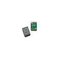
... This is 0.56” (14.22mm) height single digit display. This device utilizes AlInGaP / GaAs chip.This device is with top surface gray and white segments. Ordering Information Red Green HDSM-531C HDSM-531H HDSM-533C HDSM-533H Package Dimensions Notes: All dimensions are in millimeters (inches). Tolerance: ± 0.25mm (0.01”) unless otherwise noted. ...
Page 2
Pin Connection (Common Anode) PIN No Connection 1 Cathode E 2 Cathode D 3 Common Anode 4 Cathode C 5 Cathode DP 6 Cathode B 7 Cathode A 8 Common Anode 9 Cathode F 10 Cathode G Internal Circuit Diagram ...
Page 3
Electrical / Optical Characteristics @ T Green Parameters Average Luminous Intensity Emissions Wavelength Spectral Line Half-Width Forward Voltage, Per Segment Reverse Current, Per Segment Luminous Intensity Matching Ratio Yellow Parameters Average Luminous Intensity Emissions Wavelength Spectral Line Half-Width Forward Voltage, ...
Page 4
Typical Electrical / Optical characteristic curves @ T Green Figure 1. Relative Luminous Intensity vs. Wavelength Figure 3. Allowable DC Current vs. Ambient Temperature 4 =25°C A Figure 2. Relative Luminous Intensity vs. Forward Current Figure 4. Forward Current vs. ...
Page 5
Yellow Figure 1. Relative Intensity vs. Wavelength Figure 3. Allowable DC Current vs. Ambient Temperature 5 Figure 2. Relative Intensity vs. Forward Current Figure 4. Forward Current vs. Forward Voltage ...
Page 6
Red Figure 1. Relative Luminous Intensity vs. Wavelength Figure 3. Allowable DC Current vs. Ambient Temperature 6 Figure 2. Relative Luminous Intensity vs. Forward Current Figure 4. Forward Current vs. Forward Voltage ...
Page 7
Orange Figure 1. Relative Intensity vs. Wavelength Figure 3. Allowable DC Current vs. Ambient Temperature 7 Figure 2. Relative Intensity vs. Forward Current Figure 4. Forward Current vs. Forward Voltage ...
Page 8
Intensity Bin Limits (mcd) Green IV Bin Category Min. M 5.401 N 8.601 P 13.701 Q 21.801 Tolerance: ±15% Note: 1. Bin categories are established for classification of products. Prod- ucts may not be available in all categories. Please contact ...
Page 9
Tape specification (unit: mm) 4 ± 0.1 16 ± 0.1 For product information and a complete list of distributors, please go to our web site: Avago, Avago Technologies, and the A logo are trademarks of Avago Technologies in the United ...