EM20-FPSI 1010 LASCAR, EM20-FPSI 1010 Datasheet - Page 2
EM20-FPSI 1010
Manufacturer Part Number
EM20-FPSI 1010
Description
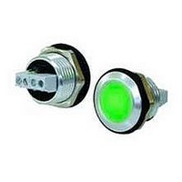
Status Indicator
Manufacturer
LASCAR
Datasheet
1.EM20-FPSI_1010.pdf
(3 pages)
Specifications of EM20-FPSI 1010
Mounting Hole Dia
20.5mm
Led Color
Red / Green
Forward Current / Color
15mA
Forward Voltage / Color
24V
Peak Reflow Compatible (260 C)
No
Accuracy
2%
Supply Voltage
24V
Ip/nema Rating
IP67 / NEMA 4X
Display Font Color
Red/Green
Leaded Process Compatible
No
Rohs Compliant
Yes
Lead Free Status / RoHS Status
Lead free / RoHS Compliant


EM20-FPSI 1010
Specifications liable to change without prior warning
CONFIGURING THE LEVEL INDICATOR
The indicator is factory configured with colour switching thresholds, as follows:
To change this setting, proceed as follows.
DIMENSIONS
CIRCUIT DIAGRAM
0.8 (0.03)
V1 = 11.0V (typ.)
V2 = 22.0V
High
Ok
Low
High
Ok
Low
Alm
V+
Vin
0V
GREEN
GREEN
Panel cut-out
RED2
RED1
RED2
RED1
100nF
47R
10k
(typ.)
V+
V2
V1
0V
V+
V2
V1
0V
ZMR50HF
2.0 (0.08)
Vreg
820R
All dimensions in mm (inches)
Store
- Remove the Store jumper link.
- Connect the V+ and 0V pins of the
- Apply the first desired voltage (V1) to Vin.
- Place the Store jumper link over the 2 pins.
- Remove the Store jumper link.
- The module flashes Green to indicate that the V1 level has been stored.
- Apply the second desired voltage (V2) to Vin.
- Place the Store jumper link over the 2 pins.
- Remove and park the Store jumper link.
- The module flashes Red to indicate that the V2 level has been stored.
- Disconnect the module. The module is now ready for use.
Step 1
Step 2
Step 3
Step 4
- To enter solid LED mode, make sure Vin does not change.
- To enter flashing LED mode, change Vin by 600mV or more.
- Place the Store jumper link over the 2 pins.
- Remove and park the Store jumper link.
- Module flashes Red or Green to indicate that the LED mode has been stored.
Step 5
FPSI 1010 to a 7.0 to 24.0Vd.c. supply.
16.5 (0.65)
jumper
link
4.0 (0.16)
2.0 (0.08)
www.lascarelectronics.com
STORE
V+
Vin
0V
EM20-FPSI 1010
Round Hole Mounting LED Status Indicator
"
8.3 (0.33)
8
5
GREEN
Issue 6
power supply
7.0 to 24.0V
input voltage
0 to 30.0V
November/2006
Do not allow bare wires to touch the metal bezel, as this may
cause a human safety hazard or damage equipment. The bare
conductor should be fully inserted into the screw terminal.
Alm
FLASHING MODE TIMING
SAFETY
V
t1
{
{
R.C. Applies to EM20-FPSI 1010/2
t2
No: 716 - Page 2 of 3
(shown in parked position)
Alm
V+
Vin
0V
jumper link
t1
Store
t1=0.1s
t2=3.6s
t(s)
Related parts for EM20-FPSI 1010
Image
Part Number
Description
Manufacturer
Datasheet
Request
R

Part Number:
Description:
Voltage Meter
Manufacturer:
LASCAR
Datasheet:


Part Number:
Description:
DPM, LED, 3.5DIGIT
Manufacturer:
LASCAR
Datasheet:

Part Number:
Description:
Voltage Meter
Manufacturer:
LASCAR
Datasheet:

Part Number:
Description:
DPM, LCD, 3.5DIGIT, NEGATIVE RAIL
Manufacturer:
LASCAR
Datasheet:

Part Number:
Description:
Voltage Meter
Manufacturer:
LASCAR
Datasheet:

Part Number:
Description:
Voltage Meter
Manufacturer:
LASCAR
Datasheet:

Part Number:
Description:
Voltage Meter
Manufacturer:
LASCAR
Datasheet:

Part Number:
Description:
Power Supply, Benchtop, 1.5 - 30Vdc (0-1 Amp)
Manufacturer:
Lascar Electronics
Datasheet: