10-5306.3255 EAO, 10-5306.3255 Datasheet
10-5306.3255
Specifications of 10-5306.3255


Related parts for 10-5306.3255


10-5306.3255 Summary of contents
Page 1
Switches and Indicators 31 31 ...
Page 2
Switches and Indicators Index Series 31 Description Product Assembly Product Range Technical Data Technical Drawing / Dimension / Layout Circuit Drawing Typical Applications Marking 36 01.2000 - pushbuttons for standard mounting - accessories / spare parts Page 37 Page 38 ...
Page 3
... Type of terminals Contact material Switch variant 31-9XX.X Lens Example: -Illuminated pushbutton, round, with momentary action; gold-plated silver contact; 1 switching element 31-131.025 -Lens, red 31-933.2 Specimen order Indicator - indicator, soldering terminal, 31-040.005 Recommended accessories: - lens, blue 31-903-6 - LED, 1 chip, 24 VDC, white 10-2312.3139 01.2000 ...
Page 4
Product Assembly illuminated-/pushbutton 38 01.2000 1 lens 2 switch housing 3 fixing nut 31 ...
Page 5
... ST = soldering terminal plug-in terminal universal terminal; PCB plug-in base page 43 marking see page 58 technical drawing as of page 51, mounting dimensions as of page 53, components layouts as of page 54, circuit drawing as of page 55 operation voltage front cap 10-26 VDC plastic black 10-55 VAC/10-75 VDC plastic black part no. ...
Page 6
... ST = soldering terminal plug-in terminal universal terminal; PCB plug-in base page 43 contacts normally closed normally open power rating: Low Level switching element: 42 V/100 mA, snap-action switching element: 250 V/5 A marking see page 58 technical drawing as of page 51, mounting dimensions as of page 53, components layouts as of page 54, circuit drawing as of page ...
Page 7
Accessories at front lens shape lens/support lens concave transparent/trans- of plastic lucent flat transparent/trans- lucent of plastic concave translucent/trans- (not for film insert lucent and LED) flat translucent/trans- lucent of plastic concave opaque/translu- (not for film insert cent and illumination) ...
Page 8
... PVC construction broad sides bent upwards narrow ends bent upwards part no. 31-920 10 0,002 e part no. 31-924 0,003 31-923 12 2 0,003 e part no. 01-927 14 0,011 01-926 13 0,011 31 ...
Page 9
Accessories blind plug colour blind plug black mounting dimensions as of page 53 at back PCB plug-in base for PCB plug-in base Low Level switching element 16.4 mm dia. x 9.8 mm high 17,9 x 8,4 mm high Low Level ...
Page 10
... 0,010 e part no. 10-1306.1349 (41-963.0) 0,001 10-1307.1369 (31-963.0) 0,001 10-1309.1309 (41-963.1) 0,001 10-1310.1319 (31-963.1) 0,001 10-1311.1249 (41-963.2) 0,001 10-1312.1229 (41-963.3) 0,001 10-1313.1209 (41-963.4) 0,001 10-1313.1249 (31-963.2) 0,001 10-1316.1179 (41-963.36) 0,001 10-1316.1209 (31-963.5) 0,001 10-1319.1179 (41-963.5) 0,001 10-1319.1199 (31-963.3) 0,001 10-1320.1179 (31-963.4) 0,001 31 ...
Page 11
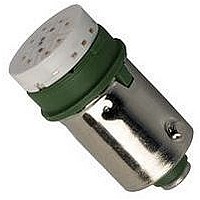
... VAC/20 mA lamp voltage Wire in accordance with local electrical safety regulations. voltage/current colour part no. 24 VDC/14 mA white 10-2312.3139 28 VDC/14 mA white 10-2313.3139 6 VDC/45 mA green 10-5306.3255 (31-968.05) red 10-5306.3252 (31-968.02) yellow 10-5306.3254 (31-968.04) 12 VDC/30 mA green 10-5309.3205 (31-968.15) red 10-5309.3202 (31-968.12) yellow 10-5309.3204 (31-968.14) 24 VAC/DC/12.5 mA green 10-5312 ...
Page 12
... V 5 spaces 10 spaces 15 spaces 20 spaces 3.3 kOhm/125/ spaces 10 spaces 15 spaces 20 spaces 10 kOhm/230-240/ spaces 10 spaces 15 spaces 20 spaces 31 e part no. 02-912.1 0,025 02-912.2 0,045 02-912.3 0,090 02-912.4 0,095 e part no. 02-914.10 0,045 02-914 ...
Page 13
Accessories dressing tool dressing tool for aligning buttons mounting tool mounting tool for tightening (or loosening) fixing nuts 31 e part no. 01-906 0,030 e 31 part no. 01-907 0,020 47 01.2000 ...
Page 14
... This low level switching element was designed for switching low powers in electronic circuits. The mechanism assures reliable switching of loads ranging from a few µA/µ 100 mA/42 VAC/ VDC. Single-break momentary contact, as normally open or normally closed with 4 independent points of contact. 2 momentary contacts per switching element ...
Page 15
... DIN IEC 68-) electrical characteristics electric strength 2500 VAC, 50 Hz, 1 min. between all terminals and earth, as per IC 512-2-11. protection class II switch rating 10 µA/100 µV to 100 VAC/VDC volume resistance starting value (initial) <= 50 mΩ rules EN 61 058 buzzer Part No. 31-810.005 switching system buzzer system ...
Page 16
... Technical Data degree of protection per IEC 529 operating temperature - 25° 55°C storage temperature - 25° 55°C (as per DIN IEC 68-) electrical characteristics frequency (tone) ca. 2.0 kHz interval frequency 2 Hz operation voltage/current 10-26 VDC; < sound pressure 88 db (A) ± distance of 0 01.2000 31 ...
Page 17
Technical Drawing, Dimension, Layout technical drawing 1 buzzer page 39 2 buzzer page 39 3 indicator page 39 4 indicator page 01.2000 ...
Page 18
Technical Drawing, Dimension, Layout 5 indicator, illuminated-/pushbutton page 39 illuminated-/pushbutton page 40 7 illuminated-/pushbutton page 40 8 AML adaptor page 41 9 AML adaptor page 41 52 01.2000 31 ...
Page 19
... Technical Drawing, Dimension, Layout 10 protective cover page 42 11 protective cover page 42 12 sprayproof cover page 42 13 protective guard page 42 14 protective guard page 42 mounting dimension 1 buzzer, indicator, illuminated-/pushbutton, blind plug page 39, 40 01.2000 ...
Page 20
Technical Drawing, Dimension, Layout 2 sprayproof cover page 42 components layouts 1 indicator, illuminated-/pushbutton page 39 PCB plug-in base page 43 3 PCB plug-in base page 43 4 PCB plug-in base page 43 54 01.2000 31 ...
Page 21
... Circuit Drawing circuit drawing circuit drawing 01.2000 ...
Page 22
... Typical Applications 1. buzzer (31-801.002) 2. buzzer (31-810.005) 56 01.2000 Depending on how the terminals are connected, the buzzer can opera- te with a continuous tone a(-) b(+) or with intermittent tone a(+) b(-) 31 ...
Page 23
Typical Applications Indicators and illuminated pushbuttons with built-in diodes With indicators and illuminated pushbuttons equipped with diodes, the user is able to perform a lamp check or wire an alarm circuit simply with a considerable saving of space ...
Page 24
... Symbols A list of the symbols available can be sup- plied on request. Horizontal mounting h s (caps) (small) 2,5 0 0,4 3 9-10 10- 7-8 5 0,5 2 5-6 6 0,6 1 4-5 58 01.2000 2. Hot stamping For large batches it is worth while to have the lettering produced by hot stamping. ...