CNY65B Vishay, CNY65B Datasheet - Page 3
CNY65B
Manufacturer Part Number
CNY65B
Description
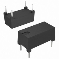
OPTOCOUPLER, TRANSISTOR, 1000VRMS
Manufacturer
Vishay
Datasheet
1.CNY64.pdf
(9 pages)
Specifications of CNY65B
No. Of Channels
1
Optocoupler Output Type
Phototransistor
Input Current
50mA
Output Voltage
32V
Opto Case Style
Through Hole
No. Of Pins
4
Propagation Delay
2.6µs
Isolation Voltage
1kV
Number Of Channels
1
Input Type
DC
Voltage - Isolation
1000Vrms
Current Transfer Ratio (min)
100% @ 5mA
Current Transfer Ratio (max)
200% @ 5mA
Voltage - Output
32V
Current - Output / Channel
50mA
Current - Dc Forward (if)
75mA
Vce Saturation (max)
300mV
Output Type
Transistor
Mounting Type
Through Hole
Package / Case
4-DIP Module
Forward Current
75 mA
Maximum Input Diode Current
75 mA
Maximum Reverse Diode Voltage
5 V
Output Device
Transistor
Configuration
1
Maximum Collector Emitter Voltage
32 V
Maximum Collector Emitter Saturation Voltage
300 mV
Current Transfer Ratio
200 %
Maximum Forward Diode Voltage
1.6 V
Maximum Collector Current
50 mA
Maximum Power Dissipation
250 mW
Maximum Operating Temperature
+ 85 C
Minimum Operating Temperature
- 55 C
Lead Free Status / RoHS Status
Lead free / RoHS Compliant
Lead Free Status / RoHS Status
Lead free / RoHS Compliant, Lead free / RoHS Compliant
Available stocks
Company
Part Number
Manufacturer
Quantity
Price
Company:

Part Number:
CNY65B
Manufacturer:
VISHAY
Quantity:
2 195
Part Number:
CNY65B
Manufacturer:
TFK
Quantity:
20 000


Note
• According to DIN EN 60747-5-2 (see fig. 2). This optocoupler is suitable for safe electrical isolation only within the safety ratings. Compliance
Document Number: 83540
Rev. 2.1, 24-Feb-11
CURRENT TRANSFER RATIO (T
PARAMETER
I
SAFETY AND INSULATION RATED PARAMETERS
PARAMETER
Partial discharge test voltage -
routine test
Partial discharge test voltage -
lot test (sample test)
Insulation resistance
Forward current
Power dissipation
Rated impulse voltage
Safety temperature
C
with the safety ratings shall be ensured by means of suitable protective circuits.
/I
F
250
225
200
175
150
125
100
75
50
25
0
0
Fig. 1 - Safety Derating Diagram
25
I
T
SI
SI
(mA)
- Safety Temperature(°C)
50
P
SO
75 100 125 150 175 200
(mW)
For technical questions, contact:
V
V
V
IO
IO
IO
(construction test only)
t
Optocoupler, Phototransistor Output,
V
Tr
= 500 V, T
= 500 V, T
TEST CONDITION
= 500 V, T
TEST CONDITION
CE
100 %, t
= 60 s, t
amb
= 5 V, I
(see fig. 2)
Very High Isolation Voltage
= 25 °C, unless otherwise specified)
test
test
amb
amb
amb
F
= 10 mA
= 1 s
= 10 s,
= 100 °C
= 150 °C
= 25 °C
SYMBOL
optocoupleranswers@vishay.com
CNY64A
CNY65A
CNY64B
CNY65B
CNY66B
CNY64,
CNY65,
V
CNY66
PART
P
V
V
R
R
R
IOTM
T
I
pd
pd
SI
SO
IO
IO
IO
SI
Fig. 2 - Test Pulse Diagram for Sample Test According to
13930
V
V
V
IOWM
IOTM
IORM
SYMBOL
V
DIN EN 60747-5-2 (VDE 0884); IEC60747-5-5
Pd
CTR
CTR
CTR
CTR
CTR
CTR
0
MIN.
10
10
10
2.8
2.2
12
11
9
t
1
CNY64, CNY65, CNY66
MIN.
100
100
100
50
63
63
Vishay Semiconductors
t
t
t
1
3
stres
t
, t
test
, t
TYP.
2
4
t
Tr
= 1 to 10 s
= 1 s
= 10 s
= 12 s
= 60 s
TYP.
MAX.
120
250
150
12
MAX.
300
125
125
200
200
200
t
2
t
www.vishay.com
3
t
t
stres
test
t
t
4
UNIT
mW
mA
kV
kV
kV
°C
UNIT
%
%
%
%
%
%
3
Related parts for CNY65B
Image
Part Number
Description
Manufacturer
Datasheet
Request
R

Part Number:
Description:
OPTOCOUPLER, TRANSISTOR, 1000VRMS
Manufacturer:
Vishay
Datasheet:

Part Number:
Description:
357-036-542-201 CARDEDGE 36POS DL .156 BLK LOPRO
Manufacturer:
Vishay
Datasheet:
Part Number:
Description:
357-036-542-201 CARDEDGE 36POS DL .156 BLK LOPRO
Manufacturer:
Vishay
Datasheet:
Part Number:
Description:
357-036-542-201 CARDEDGE 36POS DL .156 BLK LOPRO
Manufacturer:
Vishay
Datasheet:
Part Number:
Description:
357-036-542-201 CARDEDGE 36POS DL .156 BLK LOPRO
Manufacturer:
Vishay
Datasheet:
Part Number:
Description:
357-036-542-201 CARDEDGE 36POS DL .156 BLK LOPRO
Manufacturer:
Vishay
Datasheet:
Part Number:
Description:
357-036-542-201 CARDEDGE 36POS DL .156 BLK LOPRO
Manufacturer:
Vishay
Datasheet:
Part Number:
Description:
357-036-542-201 CARDEDGE 36POS DL .156 BLK LOPRO
Manufacturer:
Vishay
Datasheet:
Part Number:
Description:
357-036-542-201 CARDEDGE 36POS DL .156 BLK LOPRO
Manufacturer:
Vishay
Datasheet:
Part Number:
Description:
357-036-542-201 CARDEDGE 36POS DL .156 BLK LOPRO
Manufacturer:
Vishay
Datasheet:
Part Number:
Description:
357-036-542-201 CARDEDGE 36POS DL .156 BLK LOPRO
Manufacturer:
Vishay
Datasheet:
Part Number:
Description:
357-036-542-201 CARDEDGE 36POS DL .156 BLK LOPRO
Manufacturer:
Vishay
Datasheet:
Part Number:
Description:
357-036-542-201 CARDEDGE 36POS DL .156 BLK LOPRO
Manufacturer:
Vishay
Datasheet:
Part Number:
Description:
357-036-542-201 CARDEDGE 36POS DL .156 BLK LOPRO
Manufacturer:
Vishay
Datasheet:
Part Number:
Description:
357-036-542-201 CARDEDGE 36POS DL .156 BLK LOPRO
Manufacturer:
Vishay
Datasheet: