OP570 OPTEK TECHNOLOGY, OP570 Datasheet - Page 3
OP570
Manufacturer Part Number
OP570
Description
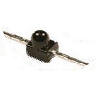
TRANSISTOR, PHOTO, NPN, 935NM, SMD
Manufacturer
OPTEK TECHNOLOGY
Datasheet
1.OP570.pdf
(4 pages)
Specifications of OP570
Transistor Polarity
NPN
Wavelength Typ
935nm
Power Consumption
130mW
Viewing Angle
25°
No. Of Pins
2
Power Dissipation Pd
130mW
Half Angle
25°
Transistor Type
Photo
Lead Free Status / RoHS Status
Lead free / RoHS Compliant
Available stocks
Company
Part Number
Manufacturer
Quantity
Price


Silicon Phototransistor
OP570 Series
OPTEK Technology Inc. — 1645 Wallace Drive, Carrollton, Texas 75006
Phone: (972) 323-2200 or (800) 341-4747
Absolute Maximum Ratings
Electrical Characteristics
Input Diode
SYMBOL
V
V
V
I
Notes:
1. Light source is an unfiltered GaAl LED with a peak emission wavelength of 935nm and a radiometric intensity level which varies less
2. To calculate typical collector dark current in µA, use the formula I
Notes:
1. Solder time less than 5 seconds at temperature extreme.
2. Derate linearly at 2.17 mW/° C above 25° C.
BR(CEO)
(BR)ECO
160%
140%
120%
100%
CE(SAT)
C (ON)
I
CEO
80%
60%
40%
20%
Storage Temperature Range
Operating Temperature Range
Collector-Emitter Voltage
Emitter-Collector Voltage
Collector Current
Lead Soldering Temperature [1/16 inch (1.6 mm) from case for 5 seconds with soldering iron]
Power Dissipation
than 10% over the entire lens surface of the phototransistor being tested.
0
Normalized at E
Conditions: V
λ = 935nm, T
On-State Collector Current
Forward Voltage
Reverse Current
Wavelength at Peak Emission
Emission Angle at Half Power Points
1.0
Relative On-State Collector
OPTEK reserves the right to make changes at any time in order to improve design and to supply the best product possible.
Ee—Irradiance (mW/cm
2.0
Current vs. Irradiance
A
CE
= 25 °C
e
= 5V,
= 5mW/cm
3.0
PARAMETER
4.0
2
5.0
(T
A
(T
FAX: (972) 323-2396 sensors@optekinc.com www.optekinc.com
= 25°C unless otherwise noted)
6.0
A
=25°C unless otherwise noted)
2
)
7.0
8.0
MIN
2.5
30
5
-
-
CEO
TYP
-
-
-
-
-
= 10
(0.04 Ta-3.4)
140%
130%
120%
110%
100%
MAX
90%
80%
70%
100
0.4
-
-
-
-25
Relative On-State Collector Current
Normalized at T
Conditions: V
λ = 935nm, T
UNITS
where Ta is the ambient temperature in ° C.
mA
nA
V
V
V
0
A
CE
= 25 °C
Temperature—(°C)
vs. Temperature
V
I
V
I
I
A
= 5V,
C
C
E
= 25°C .
CE
CE
= 100 µA
= 100 µA, E
= 100 µA
25
= 5.0 V, E
= 5.0 V, E
TEST CONDITIONS
50
E
E
E
= 5.0 mW/cm
= 0
= 2.0 mW/cm
(2)
75
-40
-25
Issue 1.2
o
o
C to +85
C to +85
130 mW
100
260° C
Page 3 of 4
2 (1)
2 (1)
20 mA
30 V
02/07
5 V
o
o
(1)
(2)
C
C
Related parts for OP570
Image
Part Number
Description
Manufacturer
Datasheet
Request
R

Part Number:
Description:
REFLECTIVE PHOTOTRANSISTOR
Manufacturer:
OPTEK TECHNOLOGY
Datasheet:

Part Number:
Description:
IR EMITTER, 890NM, T-1 3/4, THROUGH HOLE
Manufacturer:
OPTEK TECHNOLOGY
Datasheet:
Part Number:
Description:
IR EMITTER, 890NM, T-1 3/4, THROUGH HOLE
Manufacturer:
OPTEK TECHNOLOGY
Datasheet:
Part Number:
Description:
IR EMITTER, 890NM, T-1 3/4, THROUGH HOLE
Manufacturer:
OPTEK TECHNOLOGY
Datasheet:
Part Number:
Description:
IR EMITTER, 890NM, 4.65MM, TO-18-2, THD
Manufacturer:
OPTEK TECHNOLOGY
Datasheet:
Part Number:
Description:
IR EMITTER, 890NM, 4.83MM, TO-18-2, THD
Manufacturer:
OPTEK TECHNOLOGY
Datasheet:

Part Number:
Description:
IR EMITTER, 890NM, 1.9MM, SMD
Manufacturer:
OPTEK TECHNOLOGY
Datasheet:

Part Number:
Description:
IR EMITTER, 890NM, 1.9MM, SMD
Manufacturer:
OPTEK TECHNOLOGY
Datasheet:
Part Number:
Description:
DIODE, LASER, 850NM, 1.5mW
Manufacturer:
OPTEK TECHNOLOGY
Datasheet:

Part Number:
Description:
OBJECT SENSOR, DARLINGTON
Manufacturer:
OPTEK TECHNOLOGY
Datasheet:

Part Number:
Description:
TRANSISTOR PNP GP HERMETIC SMD
Manufacturer:
TT Electronics/Optek Technology
Datasheet:
Part Number:
Description:
TRANSISTOR PNP GP HERMETIC SMD
Manufacturer:
TT Electronics/Optek Technology
Datasheet:
Part Number:
Description:
TRANSISTOR NPN GP HERMETIC SMD
Manufacturer:
TT Electronics/Optek Technology
Datasheet:

Part Number:
Description:
LED IR 880NM FLAT LENS 0805 SMD
Manufacturer:
TT Electronics/Optek Technology
Datasheet:
Part Number:
Description:
NPN-Output Dc-Input Optocoupler,1-CHANNEL,1kV ISOLATION,Can-8.1
Manufacturer:
OPTEK TECHNOLOGY
Datasheet: