HSMF-C114 Avago Technologies US Inc., HSMF-C114 Datasheet - Page 3
HSMF-C114
Manufacturer Part Number
HSMF-C114
Description
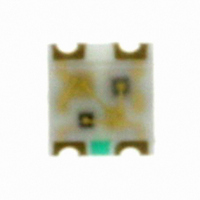
Surface-Mount/Axial LED Lamp,Blue/Bl-Gr/Or-Red,Diffused,LED-8d
Manufacturer
Avago Technologies US Inc.
Type
Tri-Colorr
Datasheet
1.HSMF-C114.pdf
(7 pages)
Specifications of HSMF-C114
Color
Red, Green, Blue (RGB)
Millicandela Rating
85mcd Red, 180mcd Green, 70mcd Blue
Current - Test
20mA
Wavelength - Dominant
626nm, 525nm, 470nm
Wavelength - Peak
637nm, 523nm, 468nm
Voltage - Forward (vf) Typ
1.9V Red, 3.4V Green, 3.4V Blue
Lens Type
Diffused
Lens Style/size
Rectangle, 1.5mm x 1.1mm
Package / Case
0606 (1616 Metric)
Size / Dimension
1.60mm L x 1.50mm W
Height
0.35mm
Viewing Angle
140°, 145°, 145°
Mounting Type
Surface Mount
Resistance Tolerance
626nm, 525nm, 470nm
Package Type
Chip Led
Emitting Color
Blue/Green/Red
Luminous Intensity
70/180/85mcd
Test Current (it)
20mA
Forward Current
15mA
Dominant Wave Length
470/525/626nm
Forward Voltage
3.9/3.9/2.4V
Product Length (mm)
1.5mm
Product Height (mm)
0.35mm
Product Depth (mm)
1.6mm
Mounting
Surface Mount
Peak Wavelength
468/523/637nm
Shape Type
Rectangular
Chip Material
InGaN/InGaN/AlGaInP
Main Category
Chip LED
Number Of Elements
3
Pin Count
4
Operating Temperature Classification
Industrial
Operating Temp Range
-40C to 85C
Reverse Voltage
5V
Power Dissipation
78/78/48mW
Lens Dimensions
1.1X1.5X0.23mm
Lead Free Status / RoHS Status
Lead free / RoHS Compliant
Luminous Flux @ Current - Test
-
Lead Free Status / Rohs Status
Compliant
Other names
516-1795-2
HSMF-C114
HSMF-C114
Available stocks
Company
Part Number
Manufacturer
Quantity
Price
Company:

Part Number:
HSMF-C114
Manufacturer:
AVAGO
Quantity:
40 000
Company:
Part Number:
HSMF-C114
Manufacturer:
AVAGO
Quantity:
50 000
Part Number:
HSMF-C114
Manufacturer:
BROADCOM
Quantity:
20 000


Electrical Characteristics at T
Part Number
AlInGaP Red
InGaN Green
InGaN Blue
Note:
1. VF tolerance: ± 0.1 V.
Optical Characteristics at T
Part Number
AlInGaP Red
InGaN Green
InGaN Blue
Notes:
1. The luminous intensity IV is measured at the peak of the spatial radiation pattern which may not be aligned with the mechanical axis of the LED
2. The dominant wavelength, ld, is derived from the CIE Chromaticity Diagram and represents the perceived color of the device.
3. q1/2 is the off-axis angle where the luminous intensity is 1/2 the peak intensity.
CAUTION:
1. The above optical performance specifications are valid
2. The above product specifications DO NOT provide any
3. Please refer to Avago Technologies’ Application Brief
3
package.
in the case when single LED is lit up.
guarantee on color mixing, color consistency over time,
or uniformity in luminous intensity when more than 1
LED is lit.
AB D-007 for additional details/explanation on driving
the part in parallel circuit.
Luminous Intensity
I
Min.
28.5
45.0
28.5
V
[1]
Forward Voltage V
@ I
Typ.
1.9
3.4
3.4
(mcd) @ 20 mA
A
F
= 20 mA
= 25°C
A
= 25°C
Typ.
85.0
180.0
70.0
F
Max.
2.4
3.9
3.9
(Volts)
[1]
Peak
Wavelength
O
Typical
637
523
468
peak
(nm)
Reverse Breakdown
V
Min.
5
5
5
R
(Volts) @ I
Color, Dominant
Wavelength
O
Typical
626
525
470
d
[2]
(nm)
R
= 100 μA
Viewing Angle
2T
(Degrees)
Typical
140
145
145
1/2 [3]
Capacitance
C (pF), @ V
Typ.
10
65
65
F
= 0, f = 1 MHz
Luminous
Efficacy
K
Typical
155
477
75
v
(lm/W)
Related parts for HSMF-C114
Image
Part Number
Description
Manufacturer
Datasheet
Request
R

Part Number:
Description:
LED CHIP GAP GREEN/YELLOW SMD
Manufacturer:
Avago Technologies US Inc.
Datasheet:

Part Number:
Description:
LED BICOLOR YLW/GN DIFF 1210 SMD
Manufacturer:
Avago Technologies US Inc.
Datasheet:

Part Number:
Description:
LED CHIP GRN/ORN 3.2X2.7MM SMD
Manufacturer:
Avago Technologies US Inc.
Datasheet:

Part Number:
Description:
LED IND RED/GRN TOP MOUNT 4PLCC
Manufacturer:
Avago Technologies US Inc.
Datasheet:
Part Number:
Description:
LED IND YLW/YGRN TOP MOUNT 4PLCC
Manufacturer:
Avago Technologies US Inc.
Datasheet:
Part Number:
Description:
LED CHIP RGB 2.5X1.0X1.0MM SMD
Manufacturer:
Avago Technologies US Inc.
Datasheet:

Part Number:
Description:
LED CHIPLED AMB/BLUE DIFF 0603
Manufacturer:
Avago Technologies US Inc.
Datasheet:
Part Number:
Description:
LED CHIPLED RED/GRN DIFF 0603
Manufacturer:
Avago Technologies US Inc.
Datasheet:
Part Number:
Description:
LED RED/GREEN/BLUE 40MCD 5V SMD
Manufacturer:
Avago Technologies US Inc.
Datasheet:
Part Number:
Description:
Standard LED - SMD Red/YGrn/Blue Tri-Color
Manufacturer:
Avago Technologies US Inc.
Datasheet:

Part Number:
Description:
LED CHIP RGB 3.2X2.7X1.1MM SMD
Manufacturer:
Avago Technologies US Inc.
Datasheet:

Part Number:
Description:
LED BICOLOR GN/HER DIFF 1210 SMD
Manufacturer:
Avago Technologies US Inc.
Datasheet:

Part Number:
Description:
LED BICOLOR HER/GN DIFF 0603 SMD
Manufacturer:
Avago Technologies US Inc.
Datasheet:
Part Number:
Description:
LED IND RED/YLW TOP MOUNT 4PLCC
Manufacturer:
Avago Technologies US Inc.
Datasheet:
Part Number:
Description:
LED IND RED/EGRN TOP MOUNT 4PLCC
Manufacturer:
Avago Technologies US Inc.
Datasheet: