SFH692AT Vishay, SFH692AT Datasheet - Page 2
SFH692AT
Manufacturer Part Number
SFH692AT
Description
Optocoupler
Manufacturer
Vishay
Datasheet
1.SFH692AT.pdf
(5 pages)
Specifications of SFH692AT
Leaded Process Compatible
Yes
Number Of Channels
1
Input Type
DC
Voltage - Isolation
3750Vrms
Current Transfer Ratio (min)
1000% @ 1mA
Voltage - Output
300V
Current - Output / Channel
50mA
Current - Dc Forward (if)
50mA
Vce Saturation (max)
1V
Output Type
Darlington
Mounting Type
Surface Mount
Package / Case
4-SOP
Forward Current
50 mA
Maximum Fall Time
14.5 us
Maximum Input Diode Current
50 mA
Maximum Reverse Diode Voltage
6 V
Maximum Rise Time
3.5 us
Output Device
Photodarlington
Configuration
1 Channel
Maximum Collector Emitter Voltage
300 V
Maximum Collector Emitter Saturation Voltage
1.2 V
Isolation Voltage
3750 Vrms
Maximum Forward Diode Voltage
1.5 V
Maximum Collector Current
50 mA
Maximum Power Dissipation
200 mW
Maximum Operating Temperature
+ 100 C
Minimum Operating Temperature
- 55 C
Lead Free Status / RoHS Status
Lead free / RoHS Compliant
Current Transfer Ratio (max)
-
Lead Free Status / RoHS Status
Lead free / RoHS Compliant, Lead free / RoHS Compliant
Available stocks
Company
Part Number
Manufacturer
Quantity
Price

Part Number:
SFH692AT
Manufacturer:
VISHAY/威世
Quantity:
20 000


SFH692AT
Vishay Semiconductors
Notes
(1)
(2)
Note
T
Minimum and maximum values are testing requirements. Typical values are characteristics of the device and are the result of engineering
evaluation. Typical values are for information only and are not part of the testing requirements.
www.vishay.com
764
amb
ABSOLUTE MAXIMUM RATINGS
PARAMETER
COUPLER
Storage temperature range
Ambient temperature range
Junction temperature
Soldering temperature
ELECTRICAL CHARACTERISTICS
PARAMETER
INPUT
Forward voltage
Reverse current
Capacitance
Thermal resistance
OUTPUT
Collector emitter leakage current
Collector emitter capacitance
Thermal resistance
COUPLER
Collector emitter saturation voltage
Coupling capacitance
CURRENT TRANSFER RATIO
PARAMETER
Current transfer ratio
Current transfer ratio
(collector emitter saturated)
SWITCHING CHARACTERISTICS
PARAMETER
Rise time
Fall time
Turn-on time
Turn-off time
T
Stresses in excess of the absolute maximum ratings can cause permanent damage to the device. Functional operation of the device is not
implied at these or any other conditions in excess of those given in the operational sections of this document. Exposure to absolute maximum
ratings for extended periods of the time can adversely affect reliability.
Refer to reflow profile for soldering conditions for surface mounted devices.
amb
= 25 °C, unless otherwise specified.
= 25 °C, unless otherwise specified.
(2)
For technical questions, contact: optocoupler.answers@vishay.com
I
I
I
I
I
I
I
I
C
C
C
C
C
C
C
C
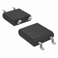
Optocoupler, Photodarlington Output,
max. 10 s dip soldering distance
= 10 mA, V
= 16 mA, V
= 10 mA, V
= 16 mA, V
= 10 mA, V
= 16 mA, V
= 10 mA, V
= 16 mA, V
to seating plane ≥ 1.5 mm
I
I
V
I
I
F
F
F
F
f = 1.0 MHz,V
V
CE
= 1.0 mA, V
= 10 mA, I
TEST CONDITION
TEST CONDITION
= 10 mA, V
TEST CONDITION
= 1.0 mA, I
TEST CONDITION
R
(1)
= 0 V, f = 1.0 MHz
= 5.0 V, f = 1.0 MHz
SOP-4 Mini-Flat Package
V
I
V
F
CE
CC
CC
CC
CC
CC
CC
CC
CC
R
= 10 mA
= 6.0 V
= 200 V
= 10 V, R
= 10 V, R
= 10 V, R
= 10 V, R
= 10 V, R
= 10 V, R
= 10 V, R
= 10 V, R
C
C
CE
CE
= 100 mA
I-O
= 10 mA
= 1.0 V
= 1.0 V
= 0 V
L
L
L
L
L
L
L
L
= 100 Ω
= 180 Ω
= 100 Ω
= 180 Ω
= 100 Ω
= 180 Ω
= 100 Ω
= 180 Ω
SYMBOL
SYMBOL
CTR
SYMBOL
V
V
CTR
R
I
R
C
CEsat
CEsat
C
CEO
C
V
t
t
t
t
I
SYMBOL
thja
thja
CE
t
t
t
t
on
on
off
off
R
CEsat
F
O
C
r
r
f
f
T
T
T
amb
T
stg
sld
j
1000
MIN.
MIN.
MIN.
500
0.3
- 55 to + 150
- 55 to + 100
VALUE
TYP.
TYP.
TYP.
0.01
20.5
53.5
100
260
750
500
1.2
6.0
1.0
1.5
14
39
Document Number: 83720
MAX.
MAX.
MAX.
14.5
200
1.5
1.0
1.2
3.5
4.5
Rev. 1.8, 16-May-08
10
29
UNIT
°C
°C
°C
°C
UNIT
UNIT
UNIT
K/W
K/W
µA
pF
nA
pF
pF
µs
µs
µs
µs
µs
µs
µs
µs
%
%
V
V
V
Related parts for SFH692AT
Image
Part Number
Description
Manufacturer
Datasheet
Request
R

Part Number:
Description:
SFH 250V
Manufacturer:
Avago Technologies US Inc.
Datasheet:

Part Number:
Description:
SFH 757V
Manufacturer:
Avago Technologies US Inc.
Datasheet:

Part Number:
Description:
SFH 551/1-1
Manufacturer:
Avago Technologies US Inc.
Datasheet:
Part Number:
Description:
SFH 250
Manufacturer:
Avago Technologies US Inc.
Datasheet:
Part Number:
Description:
SFH 757
Manufacturer:
Avago Technologies US Inc.
Datasheet:

Part Number:
Description:
357-036-542-201 CARDEDGE 36POS DL .156 BLK LOPRO
Manufacturer:
Vishay
Datasheet:
Part Number:
Description:
357-036-542-201 CARDEDGE 36POS DL .156 BLK LOPRO
Manufacturer:
Vishay
Datasheet:
Part Number:
Description:
357-036-542-201 CARDEDGE 36POS DL .156 BLK LOPRO
Manufacturer:
Vishay
Datasheet:
Part Number:
Description:
357-036-542-201 CARDEDGE 36POS DL .156 BLK LOPRO
Manufacturer:
Vishay
Datasheet:
Part Number:
Description:
357-036-542-201 CARDEDGE 36POS DL .156 BLK LOPRO
Manufacturer:
Vishay
Datasheet:
Part Number:
Description:
357-036-542-201 CARDEDGE 36POS DL .156 BLK LOPRO
Manufacturer:
Vishay
Datasheet:
Part Number:
Description:
357-036-542-201 CARDEDGE 36POS DL .156 BLK LOPRO
Manufacturer:
Vishay
Datasheet:
Part Number:
Description:
357-036-542-201 CARDEDGE 36POS DL .156 BLK LOPRO
Manufacturer:
Vishay
Datasheet:
Part Number:
Description:
357-036-542-201 CARDEDGE 36POS DL .156 BLK LOPRO
Manufacturer:
Vishay
Datasheet: