MM-2 TELEX COMMUNICATIONS, MM-2 Datasheet - Page 2
MM-2
Manufacturer Part Number
MM-2
Description
Audio Visual (audio Video), Loudspeaker
Manufacturer
TELEX COMMUNICATIONS
Datasheet
1.MM-2.pdf
(2 pages)


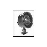
Installation
MM2
A serrated swivel mounting bracket with locking nut is furnished for
installing the MM2 and is designed so the speaker can be moved
through an angle of at least 90°. Three mounting holes are present
in the base of the mount.
MM2F
The MM2F is provided with six mounting holes 7/32 inch in diameter
around a 6.625 inch circle, to be installed behind a 6-1/8 inch
diameter hole.
Directional Performance
The directional characteristics of the MM2/MM2F were measured
by running a set of polar responses in a large anechoic chamber.
The test signal was 1/3-octave-band-limited pseudo-random pink
noise centered at the ISO standard frequencies indicated in Fig. 1.
Additional typical data is provided in Figure 2 that indicates 6 dB-
down beamwidth versus frequency for the MM2/MM2F.
www.electrovoice.com • Telex Communications, Inc. • www.telex.com
© Telex Communications, Inc. 02/2001
Part Number 38109-846 Rev A
MM2F Polar Response
Figure 1
Frequency Response
Figure 3 shows the axial frequency response of the MM2/MM2F. It
was measured at a distance of 1 meter, using a swept sine wave.
Low-Frequency Driver Protection
When frequencies below the low-frequency cutoff for the horn
assembly are fed to the driver, excessive current may be drawn by
the driver. For protection of the driver and amplifier, a capacitor in
series with driver is recommended.
150 Vdc or 150 V non-polarized electrolytic, or two 150 V electrolytics
of two times required value in series, back to back, for 70-volt lines.
MM2F Frequency Response (1 watt at 1 meter)
For drivers without transformers:
MM2F Beamwidth vs. Frequency
16-ohm driver 25 V - 100 mf
Figure 2
Figure 3
Related parts for MM-2
Image
Part Number
Description
Manufacturer
Datasheet
Request
R

Part Number:
Description:
AUDIO VISUAL,TYPES SX100+ AND SX80 2-WAY PORTABLE SPEAKER SYSTEMS,AUDIO VISUAL,AUDIO VISUAL (AUDIO VIDEO),AUDIO EQUIPMENT,TYPES SX100+ AND SX80 2-WAY PORTABLE SPEAKER SYSTEMS ,TELEX COMMUNICATIONS
Manufacturer:
TELEX COMMUNICATIONS
Datasheet:

Part Number:
Description:
Dynamic, Low Z, With Talk Bar And Locking Feature
Manufacturer:
TELEX COMMUNICATIONS
Part Number:
Description:
Dynamic, Normally Open, Low Z, Handheld Paging Mic
Manufacturer:
TELEX COMMUNICATIONS
Part Number:
Description:
DYNAMIC, NO SWITCH, LOW Z, GOOSE NECK PAGING MIC
Manufacturer:
TELEX COMMUNICATIONS