PA60 TELEX COMMUNICATIONS, PA60 Datasheet - Page 2
PA60
Manufacturer Part Number
PA60
Description
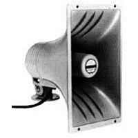
Public Address Horn
Manufacturer
TELEX COMMUNICATIONS
Datasheet
1.PA60.pdf
(2 pages)
Available stocks
Company
Part Number
Manufacturer
Quantity
Price

Company:
Part Number:
PA60305/2-2
Manufacturer:
APEX
Quantity:
9
Part Number:
PA606BA
Manufacturer:
NIKO-SEM
Quantity:
20 000
Part Number:
PA606BMG
Manufacturer:
NIKO-SEM
Quantity:
20 000
Part Number:
PA606HAG
Manufacturer:
NIKO-SEM
Quantity:
20 000
Part Number:
PA60DK
Manufacturer:
APEX
Quantity:
20 000
Part Number:
PA60EU
Manufacturer:
APEX
Quantity:
20 000


Installation
The base may be easily removed to simplify speaker installation by backing
off the single wingnut to approximately the end of its bolt. Remove the base
with a sliding motion. It is not necessary to completely remove either
the wingnut or its bolt. Later, after the base is mounted, the speaker may
be reinstalled on the base with a similar sliding motion, adjusted to any
angular position, and the wingnut tightened.
Mounting the Base
The removable mounting base has three evenly-spaced holes on a 60.3
mm (2.38 in.) diameter circle. This diameter is small enough to be
conveniently mounted on the cover of a standard 4-inch square or octagon
electrical outlet box. The base may be used as a template. In addition, the
base is slotted for mounting with 1/2-inch steel banding material. Banding
tools and materials are available commercially and permit attachment to
I-beams, pillars, or similar structural supports, where screwmounting is
impractical. Finally, the base may also be attached to many structural
supports with small C-clamps providing appropriate safety measures are
observed.
www.electrovoice.com • Telex Communications, Inc. • www.telex.com
© Telex Communications, Inc. 02/2001
Part Number 38109-845 Rev A
PA60 Polar Response
Figure 1
Polar Response
The directional characteristics of the PA60 were measured by running a
set of horizontal/vertical polar responses in Electro-Voice’s large anechoic
chamber, at each one-third-octave center frequency. The test signal was
one-third-octave pseudo-random pink noise centered at the indicated
frequencies. The measurement microphone was placed 6.1 m (20 ft.) from
the horn mouth, while rotation was about the waveguide geometric apexes.
These axes of rotation are quite close to the apparent (acoustic) apexes
across the frequency range of measurement. Errors attributable to the slight
differences between the geometric and acoustic apexes are reduced to an
inconsequential level by the relatively long, 20-foot measuring distance.
The horn was suspended freely with no baffle. The polar plots shown in
Figure 1 display the results of these tests. The center frequency is noted on
each plot. The wider plot on each chart is the horizontal polar (–) and the
narrower plot is the vertical polar (– – –).
Beamwidth
A plot of the PA60’s 6-dB-down total included beamwidth angle is shown in
Figure 2 for each one-third-octave center frequency.
Frequency Response
Figure 3 shows the axial frequency response of the PA60. It was measured
at a distance of 1 meter, using a swept sine wave.
PA60 Frequency Response (1 watt at 1 meter)
PA60 Beamwidth vs. Frequency
Figure 2
Figure 3
Related parts for PA60
Image
Part Number
Description
Manufacturer
Datasheet
Request
R

Part Number:
Description:
AUDIO VISUAL,TYPES SX100+ AND SX80 2-WAY PORTABLE SPEAKER SYSTEMS,AUDIO VISUAL,AUDIO VISUAL (AUDIO VIDEO),AUDIO EQUIPMENT,TYPES SX100+ AND SX80 2-WAY PORTABLE SPEAKER SYSTEMS ,TELEX COMMUNICATIONS
Manufacturer:
TELEX COMMUNICATIONS
Datasheet:

Part Number:
Description:
Dynamic, Low Z, With Talk Bar And Locking Feature
Manufacturer:
TELEX COMMUNICATIONS
Part Number:
Description:
Dynamic, Normally Open, Low Z, Handheld Paging Mic
Manufacturer:
TELEX COMMUNICATIONS
Part Number:
Description:
DYNAMIC, NO SWITCH, LOW Z, GOOSE NECK PAGING MIC
Manufacturer:
TELEX COMMUNICATIONS