CLUB1000-S1 RF Solutions, CLUB1000-S1 Datasheet - Page 2
CLUB1000-S1
Manufacturer Part Number
CLUB1000-S1
Description
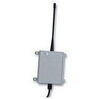
RADIO SYSTEM, 1CH, 1XTX 1XRX, 1000M
Manufacturer
RF Solutions
Datasheet
1.CLUB1000-S1.pdf
(4 pages)
Specifications of CLUB1000-S1
Svhc
No SVHC (15-Dec-2010)
Model Name / Number
Club 1000-S1
Range
1000 M
Supply Voltage Max
24VDC
Supply Voltage Min
12VDC
Lead Free Status / RoHS Status
Lead free / RoHS Compliant


DSCLUB-2 Jul ‘06
Installation Notes
Firmly fix the receiver unit approx. 2 metres from the ground, ideally in direct sight of the transmitter. Obstacles
between transmitter and receiver will reduce range! Once paired together each switch on the transmitter
operates one of the relays on the receiver unit.
Pairing Transmitter to Receiver
Each transmitter and receiver contains an address Switch. This is used to set the identity of the unit. In order
for a receiver to respond to a transmitter, the addressees must match,. This enables the user to set individual
transmitter and receivers to operate or not operate with each other. It also enables multiple systems to operate
within the same vicinity.
Each system is supplied ready configured, and does not need to be altered.
However, if you require a different address (e.g. if you have two systems in close proximity or wish to have
several receivers to one transmitter etc);
Relay Output Connections
Upto 4 relays are provided on the receiver output. The relay output provides a ‘switch’ output which operates
when the transmitter switch is pressed. Each relay has the connections as below.
Relay output ‘1’ provides a longer momentary output (approx ½ second) this may be removed (see below).
For solenoid driven traps.
The outputs are driven from a Microcontroller and can be customised to specific requirements.
Relay Output Configuration
The two option links OPT1, OPT2 (to the left of the antenna connector on the Rx PCB) set the action of the
relay outputs according to the following table. Please note that these can be customised on request.
There are 8 address ‘Switches’ which the transmitter and receiver use to identify themselves.
The Receiver and Transmitter units must have the same Address ‘Switches’ in order to recognise each
others signal.
The Transmitter switches are labelled ‘SW1’
The Receiver switches are labelled ‘LK1’
OPT1
out
out
in
in
OPT 2
out
out
in
in
Transmitter NOT Operating
½ Sec Momentary
Relay Connections when
Momentary
Latching
Relay 4
‘C
©2006 Reg. No. 227 4001, England
LUB
½ Sec Momentary
’ S
Momentary
Latching
Relay 3
Relay Connections when
Transmitter OPERATING
ERIES
Test Mode
½ Sec Momentary
Momentary
R
Latching
Relay 2
ADIO
Page 2
R
ELEASE
Momentary
Momentary
Latching
Relay 1
Related parts for CLUB1000-S1
Image
Part Number
Description
Manufacturer
Datasheet
Request
R

Part Number:
Description:
RF Switch SPDT 0MHz to 2GHz 27dB 8-Pin SOIC T/R
Manufacturer:
M/A-Com Technology Solutions
Datasheet:
Part Number:
Description:
RF Switch SPST 500MHz to 2GHz 40dB 8-Pin SOIC T/R
Manufacturer:
M/A-Com Technology Solutions
Datasheet:

Part Number:
Description:
RF Switch SPDT 100MHz to 4GHz 14dB 6-Pin SOT-6
Manufacturer:
Skyworks Solutions Inc
Datasheet:
Part Number:
Description:
RF Switch SPST 500MHz to 2.5GHz 10dB 6-Pin SOT-6
Manufacturer:
Skyworks Solutions Inc

Part Number:
Description:
IC ENCODER TRANSMITTER RF 8DIP
Manufacturer:
RF Solutions
Datasheet:

Part Number:
Description:
IC DECODER RECEIVER RF 18DIP
Manufacturer:
RF Solutions
Datasheet:

Part Number:
Description:
IC ENCODER 3 DGTL I/O SOT23-6
Manufacturer:
RF Solutions
Datasheet:

Part Number:
Description:
IC ENCODER 3 DGTL I/O 8-PDIP
Manufacturer:
RF Solutions
Datasheet:

Part Number:
Description:
IC DECODER 3 DGTL I/O 8-PDIP
Manufacturer:
RF Solutions
Datasheet:

Part Number:
Description:
IC DECODER 3 DGTL I/O 8-SOIC
Manufacturer:
RF Solutions
Datasheet:

Part Number:
Description:
118 SERIES AM REMOTE CONTROL SYSTEMS.
Manufacturer:
RF Solutions Ltd.