RF620TA RF Solutions, RF620TA Datasheet - Page 7
RF620TA
Manufacturer Part Number
RF620TA
Description
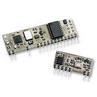
TRANSMITTER, SMART, RADIO, AM
Manufacturer
RF Solutions
Datasheet
1.RF620RA.pdf
(7 pages)
Specifications of RF620TA
Svhc
No SVHC (15-Dec-2010)


DS620-2 August ‘06
Information contained in this document is believed to be accurate, however no representation or warranty is given and R.F. Solutions Ltd. assumes no liability with respect to the accuracy of such
Mechanical Details
Antenna Design
The design and positioning of the antenna is as crucial as the module performance itself in achieving a good
wireless system range. The following will assist the designer in maximising system performance.
The RF ground pin should be connected to a ground plane which should shield the aerial connection and the
PCB layout around the aerial track itself should be such as to give a 50 Ohm impedance. The aerial should be
kept as far away from sources of electrical interference as physically possible. The specified power supply
decoupling capacitors should be placed close to the module as possible and have direct connections to the
relevant pins.
The antenna ‘hot end’ should be kept clear of any objects, especially any metal as this can severely restrict the
efficiency of the antenna to receive power. Earth planes restricting the radiation path of the antenna will also
have the same effect.
The best range will be achieved with either a straight piece of wire, rod or PCB track @ ¼ wavelength (17.3cm
@ 433.92MHz). Increased range may be achieved if this ¼ wave antenna is placed perpendicular to and in the
middle of a solid earth plane measuring at least 16cm radius. In this case, the antenna should be connected to
the module using 50 Ohm coaxial cable and the PCB track layout tips given above should be observed.
1.27
1.27
RF620R
RF620T
1
1
information. Use of R.F.Solutions as critical components in life support systems is not authorised except with express written approval from R.F.Solutions Ltd.
2.54
2.54
3
Component Side
All Trademarks acknowledged and remain the property of the respected owners
Email sales@rfsolutions.co.uk
5
25.5
SmartRadio Transmitter / Receiver
7
Tel +44 (0)1273 898 000
9
©2006 Reg. No. 227 4001, ENGLAND
10
Component Side
11
11.5
Unit 21, Cliffe Industrial Estate,
E Sussex, BN8 6JL, England
63.5
13
South Street, Lewes,
RF Solutions Ltd.,
15
Fax +44 (0)1273 480 661
3
20
http://www.rfsolutions.co.uk
Notes
Dims in mm
Pins on 0.1" pitch
Pin Dims :0.25 x 0.50 mm
25
Page 7
14.5
RF620T
RF620R
3
Related parts for RF620TA
Image
Part Number
Description
Manufacturer
Datasheet
Request
R

Part Number:
Description:
REMOTE CONTROL, 1CH, 433MHZ
Manufacturer:
RF Solutions
Datasheet:

Part Number:
Description:
TRANSMITTER, KEELOQ, 1SW, KEYFOB
Manufacturer:
RF Solutions
Datasheet:

Part Number:
Description:
RECEIVER, RX, MINI, SUPER-REGEN
Manufacturer:
RF Solutions
Datasheet:

Part Number:
Description:
RADIO SYSTEM, 1CH, 1XTX 1XRX, 1000M
Manufacturer:
RF Solutions
Datasheet:

Part Number:
Description:
RECEIVER, AM, CERAMIC
Manufacturer:
RF Solutions
Datasheet:

Part Number:
Description:
IC ENCODER TRANSMITTER RF 8DIP
Manufacturer:
RF Solutions
Datasheet:

Part Number:
Description:
IC DECODER RECEIVER RF 18DIP
Manufacturer:
RF Solutions
Datasheet:

Part Number:
Description:
IC ENCODER 3 DGTL I/O SOT23-6
Manufacturer:
RF Solutions
Datasheet:

Part Number:
Description:
IC ENCODER 3 DGTL I/O 8-PDIP
Manufacturer:
RF Solutions
Datasheet:

Part Number:
Description:
IC DECODER 3 DGTL I/O 8-PDIP
Manufacturer:
RF Solutions
Datasheet:

Part Number:
Description:
IC DECODER 3 DGTL I/O 8-SOIC
Manufacturer:
RF Solutions
Datasheet:

Part Number:
Description:
118 SERIES AM REMOTE CONTROL SYSTEMS.
Manufacturer:
RF Solutions Ltd.