T7G-434.525 QUASAR, T7G-434.525 Datasheet
T7G-434.525
Specifications of T7G-434.525


Related parts for T7G-434.525


T7G-434.525 Summary of contents
Page 1
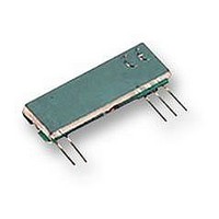
... MHz in 25KHz steps there are currently 3 different frequency channels available from stock. (others available to special order) The T7G and R7G genesis modules represent the latest generation of narrow band transmitters. They retain the same industry standard footprints and are fully compatible with the T7 and R7 modules to enable incorporation into both new and existing designs ...
Page 2
... FREQ/MHz 1 433.075(2) 18 433.925(2) 2 433.125(2) 19 433.975(2) 3 433.175(2) 20 434.025(2) 4 433.225(2) 21 434.075 (1) 5 433.275(2) 22 434.125(2) 6 433.325(2) 23 434.175(2) 7 433.375(2) 24 434.225(1) 8 433.425(2) 25 434.275(2) 9 433.475(2) 26 434.325 (2) 10 433.525(2) 27 434.375(2) 11 433.575(2) 28 434.425(2) 12 433.625(2) 29 434.475(2) 13 433.675(2) 30 434.525 (1) 14 433.725(2) 31 434.575(2) 15 433.775(2) 32 434.625(2) 16 433.825(2) 33 434.675(2) 17 433.875(2) 34 434.725( T7G / R7G Page 2 ...
Page 3
... Description SIL Transmitter 434.075MHz SIL Transmitter 434.075MHz SIL Transmitter 434.075MHz, 3 Volt version SIL Transmitter 434.225MHz SIL Transmitter 434.525MHz SIL Transmitter 434.525MHz, 3 Volt version T7G / R7G T7G Min. Max. -10°C +55°C -40°C +100°C - 5.5V - 5.5V Units Pin Notes Max. 5.5 ...
Page 4
... Description SIL Receiver 434.075MHz SIL Receiver 434.075MHz SIL Receiver 434.075MHz SIL Receiver 434.075MHz T7G / R7G R7G Min. Max. -10°C +55°C -40°C +100°C - 5.5V - +10dBm (10mW) R7G Units Notes Typ. Max P-P => ...
Page 5
... FM 433MHz Narrow Band Transmitter Connection Diagram Figure 1: Narrow Band T7 / T7G Transmitters Pin Description: RF GND (pin 1) RF ground pin, internally connected to pin 4 (0v). This pin should ideally be connected to the nearest ground plane ( e.g coax braid, main PCB ground plane etc OUT (pin 2) 50 Ohm RF antenna output ...
Page 6
... A5 D11 DATA OUT D10 DATA OUT DATA OUT VSS D8 DATA OUT 1 HT12D + VDD DOUT R OSC OSC1 OSC2 TE AD11 AD10 AD9 9 10 VSS AD8 HT12E Figure 5: FM Narrow Band Transmitter & Receiver Application Circuits Page T7G / R7G ANTENNA + GR7 ANTENNA + GT7 ...
Page 7
... FM 433MHz Narrow Band Reducing Power to 10mW If the T7G transmitter will be used with an efficient antenna in countries where only 10mW radiated power is allowed, then a simple resistive network on the output of the module will attenuate the power down to this level. Circuit Diagram 22ohm ANTENNA 220 ohm ...